
Exhibit 99.9
Confidential information has been omitted and filed separately with theSecurities and Exchange Commission. Confidential treatment has been requested with respect to this omitted information. The omitted portions of this document are indicated by [ ****].
INDEPENDENT ENGINEER’S REPORT
PURECYCLE OHIO PHASE II FACILITY
Report Prepared for:
PureCycle
Technologies, LLC
3452 Lake Lynda Dr., Ste. 151
Orlando, FL 32817
October 2, 2020
THIS PAGE HAS BEEN LEFT BLANK INTENTIONALLY
PureCycle Ohio Phase II Facility
Independent Engineer’s Report
Page i
Table of Contents
| Introduction | 1 | |
| Phase II Facility Participants | 4 | |
| Owner/Developer/Sponsor/Operator | 4 | |
| ISBL Engineering, Procurement, and Construction Contractor | 4 | |
| OSBL Engineering, Procurement, and Construction Contractor | 5 | |
| OSBL Equipment Vendors | 5 | |
| Program Manager | 6 | |
| Summary | 6 | |
| The Facility Site | 6 | |
| Site Conditions | 7 | |
| Subsurface Conditions | 7 | |
| Site Arrangement | 10 | |
| Access to Utilities | 11 | |
| Summary | 12 | |
| The Phase II Facility | 12 | |
| Civil and Structural | 12 | |
| Process Description | 13 | |
| Feedstock Pre-Processing | 13 | |
| Pre-Processed Feedstock Storage | 14 | |
| UPRP Purification | 14 | |
| Polypropylene Pellet Degassing | 16 | |
| Product Storage and Loadout | 16 | |
| Balance of Plant | 16 | |
| Water Supply and Treatment | 16 | |
| Wastewater Treatment | 16 | |
| Cooling | 17 | |
| Chilled Water | 17 | |
| Steam | 17 | |
| Hot Oil | 17 | |
| Fuel Gas | 17 | |
| Solvent | 17 | |
| Nitrogen | 18 | |
| Fire Water | 18 | |
| Instrument Air | 18 | |
| Electrical and Control Systems | 18 | |
| General | 18 | |
| Auxiliary Power | 18 | |
| Overall Control System | 19 | |
| Environmental Control Equipment | 19 |

PureCycle Ohio Phase II Facility
Independent Engineer’s Report
Page ii
| Off-Site Requirements | 19 | |
| Electrical Interconnection | 19 | |
| Water Transportation | 20 | |
| Natural Gas Transportation | 20 | |
| Nitrogen Supply | 20 | |
| Technical Review of the Phase II Facility | 20 | |
| Review of Technology | 20 | |
| Feedstock Processing | 20 | |
| PCT Technology | 22 | |
| Bench-Scale Testing Background | 23 | |
| Key Product Quality Parameters | 24 | |
| Test Procedures | 25 | |
| Bench-Scale Tests Performed | 26 | |
| Bench-scale Testing Results and Evaluation | 29 | |
| Differences between Bench-Scale Tests and the Proposed Phase II Facility (Commercial-Scale) Process | 33 | |
| Phase I Operation | 35 | |
| Phase I Design | 35 | |
| Phase I Process Data | 36 | |
| Phase I Product Quality | 39 | |
| Phase I Equipment Performance and Parameter Verification | 40 | |
| Summary | 43 | |
| Availability and Capacity Factor | 44 | |
| Estimated Useful Life | 46 | |
| Phase II Facility Performance | 46 | |
| Throughput | 46 | |
| UPRP Yield | 46 | |
| Summary | 48 | |
| Financial Model Sensitivities | 48 | |
| Construction of the Phase II Facility | 48 | |
| Construction and Equipment Supply Contracts | 49 | |
| Denham-Blythe Construction Contract | 49 | |
| Milestones | 49 | |
| Warranties and Guarantees | 50 | |
| Liquidated Damages | 50 | |
| Limits of Liability | 50 | |
| Acceptance Tests | 50 | |
| Equipment Supply Contracts | 51 | |
| KMPS Equipment Supply Contract | 51 | |
| Milestones | 51 | |
| Warranties and Guarantees | 51 |
PureCycle Ohio Phase II Facility
Independent Engineer’s Report
Page iii
| Liquidated Damages | 52 |
| Limits of Liability | 52 |
| Acceptance Tests | 52 |
| Herbold Equipment Supply Contract | 52 |
| Milestones | 53 |
| Warranty | 53 |
| Delay Damages | 53 |
| Performance Test | 53 |
| Guarantees | 53 |
| Horizon Equipment Supply Proposal | 53 |
| Milestones | 54 |
| Warranty | 54 |
| Delay Damages | 54 |
| Performance Test | 54 |
| Guarantees | 54 |
| Summary | 54 |
| Capital Costs | 55 |
| Total Construction Costs | 56 |
| Direct Construction Costs | 57 |
| Indirect Construction Costs | 57 |
| Construction Contingency | 57 |
| Summary | 58 |
| Other Project Costs | 58 |
| Financing Costs | 58 |
| Start-Up Costs and Revenues | 58 |
| Construction Schedule | 59 |
| Operations and Maintenance | 61 |
| Feedstock Agreements | 61 |
| Feedstock Agreement 1 | 62 |
| Feedstock Agreement 2 | 63 |
| Feedstock Agreement 3 | 63 |
| Feedstock Agreement 4 | 64 |
| Feedstock Agreement 5 | 65 |
| Offtake Agreements | 66 |
| Offtake Agreement 1 | 67 |
| Offtake Agreement 2 | 68 |
| Offtake Agreement 3 | 69 |
| Strategic Partnership Agreement (Strategic Partner 1) | 70 |
| Strategic Partnership Term Sheet (Strategic Partner 2) | 71 |
| Strategic Partner 3 Offtake | 71 |
| O&M Programs and Procedures | 71 |
PureCycle Ohio Phase II Facility
Independent Engineer’s Report
Page iv
| Facility Organization | 72 | |
| Non-Feedstock O&M Costs | 72 | |
| Fixed Expenses | 73 | |
| Variable Expenses | 74 | |
| Summary | 75 | |
| Owner and Other Expenses | 75 | |
| Environmental Review of the Phase II Facility | 76 | |
| Environmental Site Assessments | 76 | |
| Status of Permits and Approvals | 81 | |
| Environmental Compliance | 83 | |
| Principal Considerations and Assumptions | 84 | |
| Conclusions | 85 |
List of Figures
| Figure 1: Project Structure During Construction | 2 | |
| Figure 2: Site Location Map | 6 | |
| Figure 3: Overall Site Plan | 10 | |
| Figure 4: Block Flow Diagram | 13 | |
| Figure 5: Evolution of Process Design | 22 | |
| Figure 6: Phase Diagram of Polypropylene/Solvent Binary System | 29 |
List of Tables
| Table 1 Bench-Scale Product Specifications Average Test Results | 31 | |
| Table 2 Bench-Scale Product Quantity Results | 32 | |
| Table 3 Bench-Scale Anti-Oxidant Effect Test Results | 33 | |
| Table 4 Phase I Operating Segments and Data | 37 | |
| Table 5 Phase I Product Quality | 40 | |
| Table 6 Total Net Project Cost ($000) | 56 | |
| Table 7 Feedstock Agreement Summary | 62 | |
| Table 8 Offtake Agreement Summary | 67 | |
| Table 9 Strategic Partner Option Offtake Agreement Summary | 67 | |
| Table 10 Projected Annual Non-Feedstock O&M Expenses | 73 | |
| Table 11 Summary Status of Environmental Permits, Approvals and Assessments | 81 |
© 2020 Leidos Engineering, LLC
All Rights Reserved
THIS PAGE HAS BEEN LEFT BLANK INTENTIONALLY

Introduction
Presented herein is the report (the “Report”) of our review and analysis of a waste polypropylene processing facility (the “Phase II Facility”) to be located in Ironton, Lawrence County, Ohio under development by PureCycle Ohio LLC (the “Company”) and sponsored by PureCycle Technologies, LLC (the “Sponsor”).
The Phase II Facility will utilize a technology (the “PCT Technology”) developed by Procter and Gamble (“P&G”) and licensed to the Sponsor. The PCT Technology is to be used to process waste polypropylene for color, odor, and contaminant removal into a final product of Ultra-Pure Recycled Polypropylene (“UPRP”) that can be used in the manufacture of new plastics. The polypropylene recycling process involves four basic steps: (1) waste polypropylene receiving and handling; (2) waste polypropylene size reduction, cleaning and agglomeration; (3) contaminant removal; and (4) final processing. In the final processing phase, the polypropylene is fed into an extruder where it is melted and cut into pellets to be sold as the UPRP final product.
The PCT Technology is being implemented in a phased approach. “Phase I” refers to a pilot-scale Feedstock Evaluation Unit (“FEU”) with a capacity of 10 pounds (“lb”) per hour which was constructed by the Sponsor and entered operations in 2019. “Phase II” refers to the commercial-scale Phase II Facility that is being designed to process nominally 182 tons per day (“TPD”) of waste polypropylene. Both Phase I and Phase II are located at the same site consisting of 26 acres of land in Ironton, Ohio (the “Facility Site”). The Report is being prepared in connection with tax-exempt bond financing of the Phase II Facility. For the purposes of this Report, the “Phase II Facility” refers to the commercial-scale project.
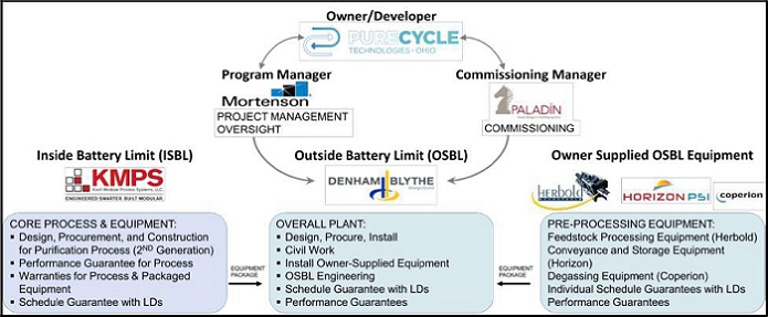
Engineering, procurement and construction (“EPC”) of the Phase II Facility is to be provided by two separate contractors. The Sponsor intends to enter into one contract with Koch Modular Process Systems, LLC (“KMPS”) to provide engineering and equipment supply for the main technology area, referred to herein as the Inside Battery Limits (the “ISBL”) under an equipment supply contract to be executed just prior to closing of the bonds (the “KMPS Equipment Supply Contract”). We have reviewed a draft version of the KMPS Equipment Supply Contract with the Sponsor dated July 15, 2020.
The construction of the remainder of the Phase II Facility, or outside battery limits (“OSBL”), including utilities and product storage is to be provided by Denham-Blythe Company (the “OSBL Construction Contractor”) under construction contract also to be executed just prior to closing of the bonds (the “Construction Contract”). The OSBL Construction Contractor intends to subcontract with EN Engineering (the “OSBL Engineering Contractor”) for engineering services. We have reviewed a draft version of the Construction Contract with the Sponsor dated July 10, 2020.
The Sponsor stated that the KMPS Equipment Supply Contract and Construction Contract are pending execution upon obtaining final financing with no additional negotiations anticipated.
The Company intends to enter a contract with Herbold Meckesheim (“Herbold”) for the supply of front-end plastics pre-processing equipment (the “Herbold Equipment Supply Contract”). The Company has obtained a fixed-price proposal from Herbold dated May 27, 2020 (the “Herbold Proposal”). HorizonPSI Inc. (“Horizon”) is to provide pneumatic conveying equipment and storage silos. Polypropylene degassing equipment is to be supplied by Coperion GmbH (“Coperion”). The Company has obtained a fixed price proposal from Horizon PSI dated May 20, 2020 (the “Horizon Proposal”) and a fixed price proposal from Coperion dated May 14, 2020 (the “Coperion Proposal”). The equipment being supplied by Herbold, Horizon, and Coperion are referred to collectively as the “PureCycle Supplied OSBL Equipment”.
550 Cochituate Road, West Wing, 4th Floor / Framingham, MA 01701 / 508.935.1600 / energy.leidos.com
PureCycle Ohio Facility
Independent Engineer’s Report
Page 2
The Company intends to contract with Paladin, Inc. (“Paladin” or “Commissioning Manager”) to lead the commissioning, start-up and acceptance testing of the Phase II Facility with the support of the Company, KMPS and the OSBL Construction Contractor. Training of the Company’s operating personnel is to be provided by a combination of Horizon, Herbold, KMPS, and the OSBL Construction Contractor for their respective equipment, and overall coordination by the OSBL Construction Contractor for equipment not provided by Horizon, Herbold, or KMPS.
The Company has contracted with M.A. Mortenson Company (“Mortenson” or “Program Manager”) to provide construction program management services. Mortenson will assist the Company with scope coordination, contract management, quality assurance, procurement, and oversight of the schedule and budget, from design through construction, commissioning, and startup of the Phase II Facility.
The overall structure of the project during the construction of the Phase II Facility is shown in Figure 1.
Figure 1: Project Structure During Construction
The Facility Site is in Ironton, Ohio on a former Dow Chemical Company (“Dow”) plant site. The Facility Site land was previously donated by Dow to the Lawrence Economic Development Corporation (“LEDC”) and includes three existing buildings (Building 504, Building 507, and Building 509) totaling 150,000 square feet that will be reused for raw material delivery, processing, and storage, and for utility equipment. An affiliate of the Company purchased the land from LEDC, and the affiliate is to sell the land to the Company at financial close for use as the Facility Site.
The feedstock is to include materials such as carpets (“fiber”), recycled polypropylene containers and other materials (“rigid material”), and biaxially-oriented polypropylene (“BOPP”) or (“film”) that is to be delivered to the Phase II Facility in various forms to include compacted bales, pellets, flakes, powder, and rolls depending on the specifications provided in each supply agreement. Provisions in the agreements allow for new types and forms of feedstocks to be added if mutually agreed. The Company reported that it has been collecting samples and test materials produced in Phase I to qualify the feedstock prior to establishing a supply agreement and using the material at the Phase II Facility. The Company intends to source feedstock from suppliers with the highest percentage of polypropylene in their materials. The Company has been operating the Phase I FEU at the Facility Site since July 2019 to confirm design parameters and to evaluate different feedstocks (see details later herein).
PureCycle Ohio Facility
Independent Engineer’s Report
Page 3
Feedstock waste polypropylene is to be supplied under the five feedstock supply agreements. The names of the feedstock suppliers are considered to be confidential by the Sponsor. For the purposes of this Report, the suppliers are referred to herein as “Supplier 1,” “Supplier 2,” “Supplier 3,” “Supplier 4,” and “Supplier 5,” (collectively, the “Feedstock Suppliers”). We have reviewed the following feedstock supply agreements: (1) an agreement with Supplier 1 dated May 19, 2018 and amended on August 20, 2018, December 12, 2018, November 11, 2019, June 12, 2020 and September 28, 2020 (“Feedstock Agreement 1”); (2) an agreement with Supplier 2 dated May 16, 2018 and amended on August 31, 2018, December 19, 2018 and June 18, 2020 (“Feedstock Agreement 2”); (3) an agreement with Supplier 3 dated May 18, 2018 and amended on August 20, 2018, December 6, 2018, September 25, 2019, and June 12 2020 (“Feedstock Agreement 3”); (4) an agreement with Supplier 4 dated May 15, 2018 and amended on August 20, 2018, November 30, 2018, October 24, 2019, and May 20, 2020 (“Feedstock Agreement 4”); and (5) an agreement with Supplier 5 dated June 4, 2018 and amended on August 20, 2018, December 4, 2018, September 12, 2019, and June 19, 2020 (“Feedstock Agreement 5”).
The UPRP offtake agreements include direct sale, direct sale to a distributer, and marketing agreements that allow for arrangement of third-party sales. There are three executed offtake agreements, and three executed strategic partnership agreements. Similar to the Feedstock Suppliers, the names of the offtakers are withheld from this Report and are referred to herein as “Offtaker 1”, “Offtaker 2”, “Offtaker 3”, “Strategic Partner 1”, “Strategic Partner 2”, and “Strategic Partner 3”(collectively, the “Offtakers”). The agreement with Offtaker 1 is dated August 30, 2017 and amended on June 29, 2018 (“Offtake Agreement 1”). The agreement with Offtaker 2 (which is also Supplier 4) is dated December 4, 2017 and amended on November 8, 2019 (“Offtake Agreement 2”). The agreement with Offtaker 3 is signed but undated; however the Company stated it was executed on May 23, 2019; and amended on October 1, 2020 (“Offtake Agreement 3”, and collectively with Offtake Agreement 1 and Offtake Agreement 2, the “Offtake Agreements”). The Company has also entered into a strategic partnership with Strategic Partner 1 under an agreement dated August 28, 2019 (the “Strategic Partnership Agreement”) for testing of product and includes the terms for a future offtake agreement to be entered into before December 31, 2020. The Company executed a term sheet for a strategic partnership with Strategic Partner 2 dated April 30, 2020 and amended on August 20, 2020 and September 24, 2020 (the “Strategic Partnership Term Sheet”). The Company reports that it has also signed several non-binding letters of intent for sale of product at premium contract prices. The Company’s three executed offtake agreements provide for a combined guaranteed minimum sale of 62.5 million pounds per year (“MMlb/yr”) of UPRP and a maximum volume of 138 MMlb/yr of UPRP at the Company’s option. The Company reported that it is in discussions with “Strategic Partner 3” as an additional strategic partner for an additional 15 MMlb/yr of UPRP offtake at the Strategic Partner 3’s option. The arrangements with the three strategic partners provide for an additional volume of 35 MMlb/yr of product offtake at the strategic partners’ option.
Operations and maintenance (“O&M”) as well as asset management of the Phase II Facility is to be provided by the Company. The Company states that the O&M agreement has been drafted; however, the asset management agreements have not been drafted at this time. The Company has developed an initial O&M plan providing the overall approach and philosophy that the Company intends to implement for the O&M of the Phase II Facility dated June 22, 2020 (the “O&M Plan”).
During the preparation of the Report, we have reviewed the Company’s approach to the EPC of the Phase II Facility and certain “Facility Agreements”, to which the Company is a party at this point in the Phase II Facility’s development. As the Independent Engineer, we have made no determination as to the validity and enforceability of any contract; however, for the purposes of this Report, we have assumed the contracts will be fully enforceable in accordance with their current terms and that all parties will comply with the provisions of their respective agreement.
PureCycle Ohio Facility
Independent
Engineer’s Report
Page 4
In addition, we have reviewed: (1) the proposed methods of construction and O&M of the Phase II Facility; (2) the methods used to estimate the cost of construction and the construction schedule; (3) projected operating capabilities of the Phase II Facility; (4) the proposed technology for the Phase II Facility; (5) the projected O&M expenses of the Phase II Facility presented in the Financial Model economic model titled “PCT_ Financial Model_07302020_v234.xlsm” (the “Financial Model”); (6) an environmental site assessment (“ESA”) of the Facility Site; and (7) the status of permits and approvals.
This Report has been prepared in accordance with a Professional Services Agreement (the “PSA”) dated as of May 9, 2017 between Leidos Engineering, LLC (“Leidos”) and the Sponsor.
During the course of our review, we have visited and made general observations of the Facility Site. The general field observations were visual, above-ground examinations of selected areas which we deemed adequate to allow us to comment on the existing condition of the Facility Site, but which were not in the level of detail necessary to reveal conditions with respect to geological or environmental conditions, safety, or conformance with agreements, codes, permits, rules, or regulations of any party having jurisdiction with respect to the Facility Site.
Certain statements included in this Report constitute forward-looking statements. The achievement of certain results or other expectations contained in such forward-looking statements involve known and unknown risks, uncertainties and other factors which may cause actual results, performance, or achievements described in the Report to be materially different from any future results, performance or achievements expressed or implied by such forward-looking statements. We do not plan to issue any updates or revisions to the forward-looking statements if or when changes to our expectations, or events, conditions or circumstances on which such statements are based, occur. No warranty, guarantee, or promise, express or implied, related to any future results, performance, or achievements associated with such forward-looking statements is provided.
Phase II Facility Participants
Those sponsors, contractors, vendors, and other major service providers responsible for the development, design, construction, and operation of the Phase II Facility are discussed below.
Owner/Developer/Sponsor/Operator
The Company is a subsidiary of the Sponsor that was established for the development of the Phase II Facility. The Sponsor is the first new company formed by Innventure, a technology development group. Innventure is focused on identifying breakthrough technology solutions that address unmet needs and have sufficient economic impact to drive and sustain changed customer behaviors. The Phase II Facility will be the first commercial-scale facility developed and operated by the Company. As such, the Company has hired a management team with expertise in running chemical facilities (Program Manager, Director of Engineering, Senior Project Leader and Senior Quality Program Leader) and recycling plants (Director of Operations).
ISBL Engineering, Procurement, and Construction Contractor
KMPS has over 25 years of experience designing and constructing mass transfer systems in areas including solvent recovery, chemical purification, steam and wastewater stripping, environmental regulation compliance, and carbon dioxide and acid gas absorption. KMPS is headquartered in Paramus, New Jersey and was established in a joint venture with Koch-Glitsch LP, a prominent supplier of mass transfer equipment in the United States (“U.S.”). KMPS has completed projects for customers in 20 countries with over 200 modular systems currently in operation. Key product purification projects designed and installed by KMPS include a commercial biodiesel purification unit in Sergeant Bluff, Iowa, an esterification and distillation system in Malaysia, and a reactive distillation unit in Bedford Park, Illinois.
PureCycle Ohio Facility
Independent
Engineer’s Report
Page 5
OSBL Engineering, Procurement, and Construction Contractor
The OSBL Construction Contractor was founded in 1976 and is headquartered in Lexington, Kentucky. The OSBL Construction Contractor has completed projects in 33 U.S. states and provides construction services in the following areas: construction management; concrete building foundations; process pit design and construction; foundation; excavation; and demolition. Prominent construction projects completed by the OSBL Construction Contractor include building additions and expansions in Kentucky, South Carolina and Rhode Island, which required relocation of utility lines, furnace additions, storm drainage and site improvements.
The OSBL Construction Contractor has subcontracted engineering to the OSBL Engineering Contractor, which was founded in 2002 as a joint venture between Nicor and Epstein Engineering. The OSBL Engineering Contractor is an engineering design firm that offers environmental, engineering and consulting services. The OSBL Engineering Contractor has experience servicing multiple clients in a range of industries including: electrical; refining; process industries; oil and liquids; natural gas, and environmental. The OSBL Engineering Contractor employs over 1,000 people who provide services throughout the U.S., with professional engineers licensed in all 50 states. Services provided by the OSBL Engineering Contractor include design, inspection, field services and survey, project management, procurement and graphical information systems. The OSBL Engineering Contractor has completed projects such as, installation and replacement of flare stacks, boiler system improvements, storm water management systems, design of electrical substations, and worked with major companies including Duke Energy Services, U.S. Steel, and ExxonMobil.
OSBL Equipment Vendors
The Company is providing three OSBL equipment packages, from vendors Horizon, Herbold, and Coperion. All of the equipment supplied under the equipment supply contracts is to be installed by the OSBL Construction Contractor who is also responsible for the procurement and installation of the remainder of the balance of plant (“BOP”) equipment. The three OSBL equipment suppliers are summarized below.
Horizon is a provider of automated ingredient handling systems and aftermarket support. Process Systems Inc., a national leader for over 25 years in design and installation of automated systems for the plastics industry, merged in April of 2016 with Horizon Systems, Inc., a 30 plus year old engineering and manufacturing company that designs innovative material handling and automated transfer solutions for food, pet food, plastics and chemical manufacturers to form HorizonPSI. HorizonPSI operates out of offices and manufacturing facilities in Lawrence, Kansas; Lenexa, Kansas; McCune, Kansas and Nokomis, Illinois. Annual sales are in the $35,000,000 range.
Herbold is a subsidiary of Herbold Meckesheim Germany, a manufacturer of size reduction, densification equipment and wash line systems for the plastics and post-consumer industry. Herbold’s North American headquarters in North Smithfield, Rhode Island specializes in the design and installation of systems for the recycling of manufacturing scrap, recycling of mixed post-consumer or industrial plastics. Its size reduction products include shredders, granulators, fine grinders and pulverizers. Wash line systems include debaling, screening, washing, dewatering and drying components to meet a variety of bottle and film applications. Herbold’s U.S. presence is staffed with sales, customer service and support, spare parts, and maintenance personnel. Global annual sales are near $39,000,000.
PureCycle Ohio Facility
Independent
Engineer’s Report
Page 6
Coperion specializes in engineering and equipment supply for compounding and extrusion; solids feeding and weighing; and materials handling. Coperion is based in Germany and has three offices in the U.S. Coperion provides engineered solutions for handling pelletized bulk materials including pneumatic and hydraulic conveying, cooling, heating, degassing, blending, separating and cleaning for the plastics industry.
Program Manager
The Program Manager was founded in 1954 and is a U.S.-based, family-owned construction company. Mortenson reports that it had approximately 5.2 billion in revenues in 2019 and over 7,500 employees. Mortenson provides a range of services such as planning, program management, general contracting, construction management and turnkey development. Mortenson has offices in Chicago, Denver, Fargo, Milwaukee, Minneapolis (headquarters), Phoenix, Portland, San Antonio, Seattle, and Washington DC.
Summary
Based on our review, we are of the opinion that Herbold, Horizon and Coperion has previously demonstrated the capability to design and supply solids processing equipment bulk handling systems, and degassing systems, respectively. KMPS, as process equipment supplier has previously demonstrated the capability to design and supply process separation equipment for chemical process facilities of similar size as the Phase II Facility, the OSBL Construction Contractor and the OSBL Engineering Contractor have previously demonstrated the capability to design and construct process facilities of similar size as the Phase II Facility. The Sponsor and the Company have not previously constructed, owned, or operated any commercial facilities of any scale; however, the Company has hired a management team with expertise in running chemical facilities (Program Manager, Director of Engineering, Senior Project Leader and Senior Quality Program Leader) and recycling plants (Director of Operations).
The Facility Site
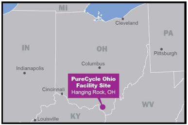
The Facility Site is located at 1125 County Road 1A (“CR 1A”) in Ironton, Lawrence County, Ohio as shown in Figure 2. The Facility Site is located approximately 100 miles south of Columbus, Ohio near the Ohio River and the State of Kentucky.
Figure 2: Site Location Map
PureCycle Ohio Facility
Independent
Engineer’s Report
Page 7
Site Conditions
The Facility Site consists of approximately 26 acres of land, which was the site of a former Dow plant. The Facility Site was previously purchased by LEDC from Dow, and later sold by LEDC to Innventure. The Company intends to purchase the site from Innventure at financial closing. The Facility Site includes three existing buildings that the Company intends to reuse for the Phase II Facility. Building 504 will be used for raw material delivery, processing, and storage. Building 507 will be used for raw material storage. Building 509 will be partially converted for utility use (the “Utility Building”).
An active Norfolk Southern Railroad (“NSRR”) mainline forms the northern boundary of the Facility Site. To the south, the Facility Site extends to CR 1A and the Ohio River, approximately 0.5 miles south of the Facility Site.
The Facility Site is comprised of generally level terrain. Per FEMA Flood Insurance Rate Map 39087C0208D, with an effective date of March 16, 2006, the Facility Site is located in Flood Zone X, an area outside the 100-year floodplain within an area of 0.2 percent annual chance of flood hazard.
Highway access to the Facility Site is convenient over national highways, state routes and county roads. Access to the Facility Site will be from U.S. Route 52 via existing access road from CR 1A. Rail access to the Phase II Facility will be provided by the NSRR. The NSRR mainline abuts the northern boundary of the Facility Site. There is an existing rail spur located on the western site boundary to the NSRR mainline where the Company plans to store empty rail cars. Additionally, the Company advises that a new rail spur will be constructed to the north of the Facility Site in order to transport finished product. Major equipment deliveries along with the feedstock will likely be transported to the Facility Site by truck/heavy hauler.
Subsurface Conditions
Subsurface investigations were performed at the Facility Site (includes the Phase I FEU and the Phase II Facility) in March 2018 and April 2020 by Consulting Services Incorporated (“CSI”) of Cincinnati, Ohio. Based on the results of its March 2018 subsurface investigations and April 2020 subsurface investigations, CSI prepared a report titled “Geotechnical Report for FEU and Commercial Plant Ironton, Lawrence County, Ohio” dated April 27, 2018 and a letter report titled “Seismic Site Class Analysis and Recommendations” dated April 16, 2020, respectively (collectively the “Final Geotechnical Reports”).
The subsurface investigations included: (1) a review of existing geotechnical data; (2) an exploration of soil and groundwater by means of 28 soil borings; (3) field and laboratory tests to aid the classification of the soils and the selection of engineering parameters and (4) geophysical surveys to aid in the determination of the seismic site class and to determine whether the soil is liquefiable. CSI prepared the Final Geotechnical Reports based on the results of the subsurface investigations. The Final Geotechnical Reports include a soil boring and test pit location plan, a summary of the field investigations, descriptions of the encountered subsurface strata, soil boring logs, and laboratory results. The Final Geotechnical Reports also include foundation design criteria for slabs, foundations, and asphalt pavement. Based on field and laboratory results, CSI also provided preliminary design parameters such as soil bearing capacity and seismic parameters. Design considerations such as corrosion potential and sulfate attack potential of the soils at the Facility Site on buried pipe or concrete in contact with soil were not addressed in the Final Geotechnical Reports; however, the Sponsor has indicated that an impressed current ground bed installed at the Facility Site will protect buried metallic structures from corrosion and that, based on its experience and CSI’s experience, past projects completed in the area of the Phase II Facility have not encountered any high-sulfide soils. The Sponsor also indicated that all base slabs and footings will be founded on a layer of crushed stone and geopiers, which will help drain water away from the structures and minimize exposure to potential sulfate attacks.
PureCycle Ohio Facility
Independent
Engineer’s Report
Page 8
The subsurface investigations included taking 30 soil borings throughout the Facility Site. Alluvial deposits consisting of an upper layer of silty clay/silt (clay) underlain by granular materials were encountered in each of the borings. The clay generally consisted of brown-to-brown and gray clay with trace roots with varying amounts of silt and fine grained sand to depths of about 12 to 15 feet below grade. At a depth of about 8 feet below grade, a silt layer was encountered in several of the borings. A layer of fine to course grained sand with varying amounts of clay and gravel was noted below the clay and silt layers in nearly all of the borings.
Index properties of the silt layer derived from laboratory testing of several representative samples taken during the March 2018 subsurface investigations indicated that the silt layer encountered in several borings is susceptible to liquefaction occurring during an earthquake event, which could result in settlement of the ground surface, lateral spreading of the ground, or both when the silt layer loses strength as a result of an applied seismic-induced load. However, given the results of the April 2020 geophysical surveys, CSI concluded that the silt layer is not liquefiable and that the use of geopiers are needed to support foundations, but for bearing condition support and settlement resistance only.
Groundwater was encountered in two borings at a depth of approximately 24 feet below ground surface. The Final Geotechnical Reports notes that the elevation of groundwater depends upon recent rainfall activity and subsurface drainage patterns in the area that may change depending on climatic conditions. The Final Geotechnical Reports also notes that given the granular nature of the material below the clay and silt layers the groundwater table is likely to be hydraulically connected to the Ohio River and will likely fluctuate with that of the river.
Based on the results of the April 2020 geophysical surveys, CSI recommended a Seismic Site Class D, a stiff soil profile, with spectral accelerations of SS and S1 of 0.151 and 0.073 times the acceleration of gravity (“g”), respectively; these spectral acceleration values indicate that the Facility Site is located in an area of moderate seismic activity. The Final Geotechnical Reports identify a small unnamed fault that exists in the direct vicinity of the Facility Site and a second unnamed fault approximately 10 miles to the north. In the review of mapped historical earthquakes, CSI noted in the Final Geotechnical Reports that five earthquakes have occurred within about 20 miles of the site dating back to 1883 ranging in Richter magnitude between 2.0 (mild and rarely felt by people) to 5.4 (moderate).
Due to excessive settlement potentially occurring as the clay layer consolidates under structure loading, CSI recommended mat foundations for the silos, the water tank for the fire suppression system (the “fire water storage tank”), flare stack and the KMPS processing modules be installed after the areas of those foundations are preloaded (surcharged) with fill to a height of about 8 to 15 feet if the construction schedule permits or be installed on rammed aggregate piers. To support lighter structures or equipment such as pre-engineered structures, small tanks, and miscellaneous support structures, CSI recommended shallow spread footings; CSI did not recommend the areas of these foundations be surcharged or placing these foundations on rammed aggregate piers.
PureCycle Ohio Facility
Independent
Engineer’s Report
Page 9
With respect to concealed site conditions, the Construction Contract contains the usual exclusions that require the OSBL Construction Contractor to acknowledge that it is obligated to conduct additional investigation of the Facility Site to determine its suitability for construction of the Facilities and performance of the work; that the OSBL Construction Contractor has made all investigations and inspections that it deems necessary to perform the work in accordance with the project schedule; and the OSBL Construction Contractor understands the climate, terrain, and other difficulties that it may encounter in performing the Work in accordance with the project schedule. In addition, the Construction Contract requires the Company to provide to the OSBL Construction Contractor a list of all known concealed conditions (including rock excavation, removal or relocation of hidden utilities, and mediating subsurface issues) at the Facility Site prior to issuing the Notice to Proceed (“NTP”).
Based on our review, we are of the opinion that provided that the OSBL Construction Contractor follows the recommendations by CSI in the Final Geotechnical Reports regarding site development, access, subsurface conditions, and ground improvements and implements good quality control of the earthworks and foundation settlement monitoring during construction under the direction of the geotechnical engineer of record, the Facility Site should be suitable, from an infrastructure and geotechnical perspective, for construction, operation, and maintenance of the Phase II Facility.
PureCycle Ohio Facility
Independent
Engineer’s Report
Page 10
Site Arrangement
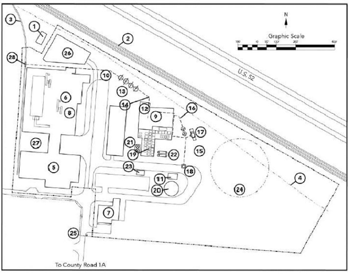
Figure 3 shows the overall arrangement of the Facility Site.
Figure 3: Overall Site Plan
LEGEND
|
1. Existing AEP Substation 2. Railroad Main Line 3. 1,200' Railroad Spur 4. Gas Transmission Line 5. Raw Material Storage 6. Raw Material Processing and Storage 7. FEU Building 8. Raw Material Processing Equipment 9. Finished Product Processing Building/Maintenance Building 10. Raw Material Conveyor 11. Water Pump Building 12. Control Room 13. Raw Material Silos 14. Raw Material Conveyors |
15. Finished Material Silos 16. Finished Material Conveyor to Silos 17. Finished Material Rail Loading with Scales 18. Truck Loading Structure 19. Commercial Plant Processing Modules 20. Water Storage Tank 21. Cooling Tower [*****] 23. Nitrogen Unloading and Storage 24. Flare Zone 25. Security Gate and Guardhouse 26. Relocated AEP Substation 27. Outdoor Storage Area 28. Raw Material Rail Unloading with Scales |
Source: Site arrangement courtesy of the Company.
PureCycle Ohio Facility
Independent
Engineer’s Report
Page 11
Access to Utilities
Electric service for the Phase II Facility will be provided by American Electric Power (“AEP”) at the northeast section of the Facility Site, near the existing Dow Substation. Service will be provided at the sub-transmission level, 69 kilovolts (“kV”). The 69 kV circuit to the Facility Site will be connected at a three-way switched tap using a manual disconnect switch for the 69 kV circuit between two new motor operated switches in the existing AEP line between the Highland and Dow Chemical-Hanging Rock Substations, allowing power to be fed from either transmission line segment. AEP will provide metering at the switched tap. The capacity of the new service will accommodate the Facility Site’s anticipated load of [*****] MW. The 69 kV circuit will connect to a Company owned substation to be transformed to 4,160 V by a single 15 MW transformer. Larger loads within the Phase II Facility will be powered at the 4,160 volt (“V”) level. The 4,160 V will be transformed to lower voltages to serve smaller loads. The gas line on the northern boundary of the Facility Site is dedicated to a nearby Luminant power station and will not be used by the Phase II Facility.
The Company has entered into a memorandum of understanding (“MOU”) with Constellation New Energy, Inc. (“Constellation Electric”) dated June 8, 2020 (the “Constellation Electric MOU”) to supply [*****] megawatt-hours per year of electricity to the Phase II Facility for a 5-year period starting in September 2021. Under the Constellation Electric MOU, the energy price is fixed; however, the Company is responsible for demand, transmission, distribution charges and riders charged by the local power retail supplier (AEP). For the purpose of our review of the O&M costs, we have assumed that the Company and Constellation Electric will enter into a definitive contract based on the terms of the MOU and that the Company will pay an additional equivalent amount for the other power charges as set forth in the AEP “GS4 Subtransmission Open Access Distribution” rate schedule.
The Phase II Facility is expected to interconnect to an existing gas pipeline owned by TransCanada/Columbia located to the west of the Facility Site. This pipeline is located approximately 1,800 feet to the west of the Facility Site and will require approximately 1,800 feet of new additional easements or rights-of-way. The Company advised that TransCanada/Columbia is to be responsible for the acquisition of the required easements/rights-of-way, but that no work has been performed by Columbia to date. Natural gas is to be transported by TransCanada/Columbia at a pressure of [*****] pounds per square inch gauge (“psig”) through a pressure letdown station to be installed. The maximum available natural gas from TransCanada/Columbia is [*****] standard cubic feet per hour (“MSCFH”) at [*****]. British thermal units (“Btu”) per standard cubic foot (“Btu/scf”) without any additional compression.
Natural gas is to be supplied Constellation NewEnergy – Gas Division, LLC (“Constellation Gas”). The Company has entered into an MOU with Constellation Gas dated June 8, 2020 (the “Constellation Gas MOU”). The Constellation Gas MOU anticipates that a binding agreement is to be negotiated between the parties for the supply of a contract quantity of natural gas by Constellation Gas starting in September 2021. The estimated contract quantity is [*****] dekatherms (“Dth”) per year (approximately [*****] per hour on an average basis or [*****] MSCFH). The first 3 to 5 years would be New York Mercantile Exchange (“NYMEX”) commodity plus basis at a fixed price, and the next 10 to 12 years priced at NYMEX settlement for commodity with a floating basis price. The Company would have the ability to lock in portions of the floating basis at different times as the Company’s liquidity allows and the parties agree. Pricing for those volumes above or below the requested quantity is to be priced at a then-relevant spot market price.
PureCycle Ohio Facility
Independent
Engineer’s Report
Page 12
Potable and raw water is to be provided by the city of Portsmouth, Ohio municipal water system. The Company advised that the LEDC is constructing a new water line along CR 1A to the Facility Site entrance and will be responsible for the acquisition of the required easements/rights-of-way related to potable water line construction. No water will be drawn from the Ohio River.
Sanitary sewage, process wastewater, and process area rainwater is to be pre-treated in an on-site plant prior to discharge. The Company has an MOU with the Scioto County Board of Commissioners (the “County”) dated May 23, 2019 for discharge of the pre-treated wastewater to the County publicly owned treatment works (“POTW”). The County is to design, install, own, operate, and maintain the infrastructure and metering required to collect wastewater from the Phase II Facility. The Company is to reimburse the County for the construction costs, up to a maximum of $1,750,000. The Company is also responsible for the costs associated with the installation of the tap at the point of receipt. Under the MOU, the maximum flow is [*****] gallons per day and meet applicable effluent standards of the Ohio Environmental Protection Agency (“OEPA”). The rate to be paid by the Company is [*****] gallons.
Summary
Based on our review of the equipment arrangement layout, the Facility Site is of adequate size to support the construction, operation, and maintenance of the Phase II Facility, and provides sufficient access to utilities.
The Phase II Facility
Civil and Structural
The Design Basis Manual (“DBM”) for the Phase II Facility identifies the 2015 IBC as governing the civil, structural, and architectural design of the Phase II Facility. The buildings provided by the OSBL Construction Contractor include a guardhouse/truck scale house, a Control Room, a Finished Product Processing Building/Control Room, and limited restoration of the existing buildings: Building 504, Building 507, and Building 509 (Utility Building). The OSBL Construction Contractor constructed the Phase I building under a separate contract. The Maintenance Building will be part of one of the existing buildings.
As previously discussed, the Final Geotechnical Reports recommended mat foundations for the silos, tank, flare stack and the KMPS processing modules be installed after the areas of those foundations are preloaded (surcharged) with fill to a height of about 8 to 15 feet if the construction schedule permits or be installed on rammed aggregate piers; shallow spread footings founded on natural soils (not on fill) were recommended for lighter structures and equipment such as pre-engineered structures, small tanks, and miscellaneous support structures. Considering the concern of the clay layer consolidating under significant gravity loads introduced by the buildings, equipment and storage products for the mat foundations occurring as the relatively thin silt clay/silt layer consolidates under structure loading, the Construction Contract scope book indicates a ground improvement technique involving the installation of rammed aggregate piers will be completed in the area of the storage silos, the fire water storage tank, KMPS processing modules, and the pipe bridge to the flare stack. The Sponsor indicated that lighter structures such as pre-engineered structures, small tanks, and miscellaneous support structures will be founded on shallow spread footings, which is consistent with recommendations made in the Final Geotechnical Reports.
PureCycle Ohio Facility
Independent
Engineer’s Report
Page 13
Regarding vibration design criteria, the Sponsor indicated that the OSBL Engineering Contractor will utilize API guidance documents for vibratory equipment foundation design such that the foundation loads for rotating and reciprocating equipment will be four to five times the equipment weight and sleeved anchors will be utilized to minimize vibration translation to the underlying soil strata. Where heavy dynamic loads will exist, the OSBL Construction Contractor will install rammed aggregate piers approximately 12 feet in depth to a layer of sand that will protect the equipment foundation from settlement of the clay layer as a result of consolidation or settlement of the silt layer as a result of liquefaction.
With respect to settlement, the Sponsor reported that it expects allowable total settlement of 1 inch or less, 0.75 inch of differential settlement between columns, and 0.75 inch of differential settlement for every 30 feet of continuous foundations and has indicated that these values have been assumed in the design of foundations. To limit settlement occurring in the clay layer that extends to depths of approximately 12 to 15 feet below grade, which the Sponsor has estimated to be on the order of magnitude of 3 to 5 inches based on consolidation test results, the Sponsor indicated that the footprints of the mat foundations for the silos, the fire water storage tank, flare stack and the KMPS processing modules will be surcharged or these mat foundations will be founded on rammed aggregate piers in those areas.
Preliminary specifications specify seismic design mapped spectral accelerations of SS = 0.151 g, S1 = 0.073 g, and Site Class D for the seismic design, which is consistent with the values determined in the Final Geotechnical Reports. The Preliminary structural drawings identify the basic design wind speed of 120 miles per hour, with an Exposure Category “C” which correlates to open terrain. Further, with respect to winter conditions, the “Plant Site Data Sheet” specifies a design ground snow load of 20 psf. The DBM notes that all pre-engineered metal buildings have been designed strictly for environmental loads such as wind and snow and that the only building designed to meet blast criteria is the Control Room located adjacent to the Finished Product Processing Building.
Process Description
The following process description is based on process flow diagrams provided by the Company. An overall block flow diagram of the Phase II Facility process is shown in Figure 4.
Figure 4: Block Flow Diagram
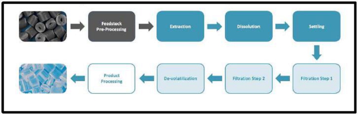
Feedstock Pre-Processing
The Phase II Facility is to receive three types of feedstock: (1) prewashed flake which is ready to be fed to the main process; (2) high purity feedstock (containing greater than 95 percent polypropylene) which needs minor pre-processing; and (3) rigid material or film material which requires more extensive process to clean and size the polypropylene. All feedstock is to be delivered by truck.
PureCycle Ohio Facility
Independent Engineer’s Report
Page 14
The feedstock is to be received in bales. There are two high-purity lines, each of which can process either 8,800 pounds per hour (“pph”) of rigid plastics, 5,500 pph of plastic film and 4,400 pph of plastics fibers and a separate wash line (described below) can also process 8,250 pph rigid plastics (producing 6,600 pph of clean product) or 3,880 pph of film plastic (producing 3,300 pph of clean product). The baled material is debaled by removing the tie wire then size reduced in a shredder. The shredded material is sent to temporary storage and passed by a metal detector, which activates valves to reject the metal containing material prior to the granulator. The material is then further size reduced in a granulator. This sized material is conveyed to one of six agglomeration units where the plastic is heated to its softening point and slightly compacted. Each unit is sized to process 2,640 pph of material. This compacted material is sent via pneumatic transport to the storage silos.
The rigid or film material, which needs a higher level of cleaning, is received in bales. This material is processed in the wash line. The wash line can produce either 6,600 pph of rigid material or 3,300 pph of film material. The material is debaled, fed to a wet shredder, reduced in size to 80 millimeters (“mm”), conveyed to a wash system containing a heavy material separation and rinse steps to remove contaminants and conveyed to temporary storage. The temporary storage allows for a uniform flow of material to the subsequent processing steps. The sized material then goes through a dry prewash drum to separate coarse contaminants via density, a wet grinder to reduce the particle size to 20 mm to optimize further processing. This small material then goes to a float/sink tank to remove heaver plastics, such as polyethylene terephthalate (“PET”), polyvinyl chloride (“PVC”), and acrylonitrile butadiene styrene (“ABS”) and other dense material. The float material is then dried in a centrifugal-type mechanical dryer, followed by a screw-type dewatering press and finally a thermal dryer. The final moisture content after drying is to be approximately 0.5 percent. The dried material is then heated to its softening temperature, or approximately 160 degrees Celsius (“°C”) and compacted to increase the bulk density. This cleaned material is then sent to intermediate storage. The wash line is designed to produce approximately 6,600 pph of clean feedstock from the 8,250 pph of incoming rigid feed or 3,300 pph of clean film material form 3,880 pph of input. The wash line has auxiliary equipment to clean the wash water and dispose of reject material.
All of the processed material is sent to pre-processed feedstock storage, prior to being sent to the main purification process or back to packaging.
Pre-Processed Feedstock Storage
The storage facilities include four pre-processed feedstock storage silos, each with a nominal working volume of 45,000 cubic feet, equivalent to approximately 10.4 to 12.3 days (depending on feedstock density) of pre-processed feedstock storage.
UPRP Purification
The PCT Technology is based on the capability of a certain hydrocarbon solvent, at certain conditions, to extract soluble items from the polypropylene at one temperature and subsequently when the temperature is dropped, allow insoluble items to fall out of the mixture. In the process, the polypropylene feedstock pellets or flakes are transferred from the storage silos to several feed hoppers. The hoppers are purged with nitrogen gas to drive off moisture and any contained air. From here, the polypropylene is metered into two parallel continuous melting extruders. The polypropylene is heated in the extruders to [*****]. There is also a feed hopper for the addition of an additive to the polypropylene in the extruders. Each extruder package has a screen to remove large solids and a drum filter to remove finer solids, followed by a melt pump. The high pressure melted polypropylene from each extruder package is combined and sent to a lights extraction column.
PureCycle Ohio Facility
Independent Engineer’s Report
Page 15
In the lights extraction column, a separate flow of pure solvent (three times that of the total incoming feed flow) is passed up in countercurrent direction to the feed for extraction and removal of the light, soluble impurities. The impurity-laden solvent flow is taken off the top of the column and sent to a flash tank where the impurities and a small amount of dissolved polypropylene are separated out and the solvent is recovered for reuse via a distillation column and the solvent recycle tank.
The polypropylene-solvent flow leaving the bottom of the lights extraction column is pumped to a mixing column where additional solvent and a small amount of recycled polypropylene from downstream are added and mixed with the polypropylene and cooled until a single phase is formed, fully dissolving the polypropylene in the solvent. The flow from the mixing column then enters a settler, a decanter vessel in which heavy, insoluble impurities such as polyethylene are allowed to settle out by gravity. The heavy phase at the bottom of the vessel is conveyed out of the settler and fed to a melt pump into a melt pipe. In the melt pipe, the solvent is offgases and a solid strand of polypropylene, polyethylene, and solid impurities is formed which is fed into a water bath, and conveyed to a cutter to cut the strand of byproduct solid polymer (referred to as byproduct) waste product into pieces for collection to be sent to scrap storage. The degassed solvent is sent to the devolitization vacuum system for recovery.
The polypropylene/solvent flow from the top of the settler is passed through one of two candle filters to remove remaining insoluble solid impurities such as color pigments. One filter is operational at any given time while the other is being cleaned, prepared, or on standby. Once the filter is taken off-line for cleaning, a solvent flow is first used to remove any residual polypropylene (which otherwise would solidify and plug the unit upon pressure letdown) in the filter. The residual polypropylene is recycled back to the mixing column upstream via a collection tank (melt drum). A gas is then used for filter blowback to remove the accumulated solids coating. The solids fall to the bottom of the filter housing, are sent to a ribbon blender and are removed by a belt conveyer.
The polypropylene/solvent solution leaving the filter then passes through one of two adsorption columns. The columns are packed with adsorbent material intended to remove the last of the impurities in the polypropylene not already removed by the upstream unit operations. One column is operational at any given time while the other is being cleaned, reloaded with adsorbent, or on standby. When a column is taken off-line at the end of its operating cycle, the column is first purged with solvent to remove residual polypropylene. The residual polypropylene is recycled back to the mixing column upstream via a collection tank (melt drum). The spent adsorbent is then removed from the column and transported by a vibratory conveyer as a waste stream before reloading with fresh adsorbent.
After leaving the adsorption column, the now purified polypropylene/solvent solution is reheated and then enters a decanter vessel where the polypropylene comes out of solution. The separated solvent exits the top of the vessel and is pressurized before being recycled back to the extraction and mixing columns. The molten polypropylene phase leaves the bottom of the vessel as a mixture of polypropylene and solvent and is sent to a devolatilization tank in which the pressure is reduced, removing a large portion of the solvent, and the flashed solvent is recovered for reuse in the process. The liquid phase then enters a devolatilization/product extruder where the remaining solvent is removed from the polypropylene phase and recycled back for reuse in the process after purification. A series of additive compounds are metered from a single hopper, and sent to an additive extruder package and then added to the polypropylene in the product extruder. The polypropylene is then extruded, reduced in pressure, and then sent to an underwater pelletizer followed by a centrifugal dryer. The polypropylene product pellets are passed through a classifier, with proper size pellets sent to storage and out-of-spec pellets recycled back to the extruder for reprocessing via the additive feed line. The product polypropylene is pneumatically conveyed to either a quality control holding silo or to the polypropylene pellet degassing system.
PureCycle Ohio Facility
Independent Engineer’s Report
Page 16
Polypropylene Pellet Degassing
The purpose of the degassing system is to remove volatile components (such as solvent) from the product polypropylene pellets. The degassing system consists of a heat exchanger for heating the pellets designed for vertical gravity flow of the pellets with the heating medium (hot oil) flowing through tubes within the shell. The pellets then flow downward into a degassing silo, with first-in, first-out flow. From the degassing silo, the pellets flow into another heat exchanger of similar design as the one heating the pellets, except in this case using cooling water in the tube to cool the pellets prior to transfer to the storage silos.
Product Storage and Loadout
The finished product storage consists of storage, loading units and support equipment intended to support the sale of UPRP produced at the Phase II Facility.
The product UPRP pellets are to be conveyed to one of three finished product storage silos, each with a nominal capacity of 20,000 cubic feet. Additional storage is to be provided by 21 rail cars of 6,250 cubic feet each, resulting in approximately 17 total days of finished product storage. From storage, the UPRP pellets are to be conveyed into one of two 7,000 cubic foot blending silos for loading of railcars. Any non-prime pellets will be sold as non-prime or reintroduced into the system for reprocessing.
All polyethylene/polypropylene scrap are to be conveyed at to a polypropylene scrap silo or to takeoff dumpsters, which will be periodically conveyed into a bulk truck loading hopper, or landfilled.
Balance of Plant
Water Supply and Treatment
Potable water will be supplied from Portsmouth municipal water system via the LEDC pipeline and is to be used for potable, fire, and process water for the Phase II Facility. A 500,000-gallon fire water storage tank is to be provided for firewater storage. The potable water is to be used untreated in the Phase II Facility’s cooling towers, pelletizers, materials handling system, safety showers, and as make-up to the Phase I chilled water system and water softener units.
There are to be two water softener units using conventional technology, each to provide softened water to the auxiliary boilers for the production of [*****] pph of steam.
The total average water requirement to the Phase II Facility is estimated by the Company to be approximately [*****] gallons per minute (“gpm”), which includes [*****] gpm of cooling tower make-up.
Wastewater Treatment
Process wastewater and process area contact rainwater is to be pre-treated on-site prior to discharge to the County POTW. The expected flow is [*****] gallons per day of sanitary water and [*****] gpm of process wastewater. The pre-treatment is to be provided as part of the Construction Contract and is to consist of a plastic separator/screener, an oil/water separator, an equalization tank, and pH control. The wastewater is to be pumped through a sampling station and metering station and sent to the County POTW.
Sources of process wastewater include cooling tower blowdown, boiler blowdown, material handling wastewater, water softener blowdown, instrument air driver/receiver blowdown, safety shower water, and fire water supply pump test water. Storm water is to be stored in a holding pond with a capacity of [*****] gallons for major storm events to regulate flow to the wastewater treatment facility.
PureCycle Ohio Facility
Independent Engineer’s Report
Page 17
Sanitary wastewater from restrooms, showers and the laboratory facilities will also be discharged to the County POTW.
Cooling
The Phase II Facility is to have two induced draft, crossflow cooling towers. The design capacity for the cooling tower loop is [*****] at [*****] with an average cooling water loop flow of [*****] gpm. The cooling tower will operate at five cycles of concentration. The cooling water will be circulated with three cooling water pumps, each sized for the average flow. During normal operation, only two of three pumps would be required.
Chilled Water
The chiller system includes two chiller packages, each with a capacity of [*****] refrigeration tons for a total capacity of [*****] refrigeration tons of cooling. The peak refrigeration load of the KMPS modules is [*****] tons and the OSBL will require a peak load of [*****] tons of chilling, for a total peak chilling load of [*****] tons. The circulating fluid is to be [*****] heat transfer fluid with a supply temperature of [*****] and a return temperature of [*****].
Steam
The Phase II Facility is to have three natural-gas-fired steam boilers, each rated at [*****] pph of steam at [*****] psig for a total capacity of [*****] pph. The steam is to be used at two pressure levels, [*****] psig and [*****] psig. The [*****] psig steam will be provided from letdown stations from the [*****] psig steam system. The steam users include the solvent heater, jacketed vessels and piping, a deaerator for deaerating the returning steam condensate, the railcar wash system, and the flare. Steam is also used in the materials handling section of the Phase II Facility for material preprocessing to provide additional drying for fiber or film. The average Phase II Facility steam usage is estimated to be approximately [*****] pph. The total peak Phase II Facility steam demand is estimated to be approximately [*****] pph.
Hot Oil
The hot oil system will include [*****] natural gas fired hot oil heaters sized for [*****] Btu per hour each, two hot oil recirculation pumps, each sized for a single heater, and one hot oil expansion/storage tank. The estimated peak hot oil demand is approximately [*****] Btu per hour.
Fuel Gas
Natural gas will be used for heating of Building 504, Building 507, the Finished Product Processing Building, the Utility Building, the Phase I Building, and as fuel to three steam boilers, two hot oil heaters and to the flare as pilot gas and assist gas. The Company has estimated the total average usage of natural gas to be approximately [*****] MSCFH.
Solvent
Solvent is to be delivered to the Phase II Facility by truck. The solvent system is to be located outdoors and designed to provide and average flow of [*****] pph and a peak flow of up to [*****] pph of solvent to the process. The solvent system is to consist of an [*****]-gallon solvent storage tank, [*****] contaminated solvent storage tanks, one solvent unloading pump, and [*****] solvent feed pumps, each sized for maximum flow.
PureCycle Ohio Facility
Independent Engineer’s Report
Page 18
Nitrogen
The Company intends to lease a nitrogen generation unit designed to provide a peak loading of [*****] (“SCFM”) of nitrogen at a minimum of [*****] psig. The Company currently has a lease agreement with Praxair for nitrogen supply for Phase I, and intends to contract with Praxair for the nitrogen supply for the Phase II Facility. Due to safety concerns related to power outages, a singular compressed tank of nitrogen will be available for use.
Fire Water
The fire water system is to consist of a fire water supply system, a [*****] gallon fire water storage tank, a steam heater for the firewater storage tank, two diesel powered fire water supply pumps sized for [*****] gpm each, an electric jockey pump, fire hydrants, fire monitors, and necessary sprinkler systems for Building 504 and Building 507, the Finished Product Processing Building, the Utility Building, and a deluge system for the process area by KMPS.
Instrument Air
The instrument air system is to consist of three electric oil-free air compressors designed to deliver up to [*****] SCFM at [*****] psig and is to include two desiccant air dryers, and one air receiver vessel.
Electrical and Control Systems
General
The review of the electrical and control systems of the Phase II Facility is based on the Construction Contract scope of work document and the Company’s clarifications. The electrical design of the Phase II Facility is to be in accordance with National Electrical Manufacturer’s Association, National Fire Protection Association (“NFPA”), the National Electric Code-NFPA 70, American National Standards Institute standards, and International Electrotechnical Commission (“IEC”). The required design calculations are to include short circuit, load flow, soil resistivity and grounding, protective device coordination, and arc flash, voltage drop, conduit heating, conduit and cable tray fill, lighting level, and hazardous area classification studies. In addition to the power distribution systems described below, additional systems including grounding, cathodic protection, lightning protection, lighting systems, communications, controls, emergency power are to be included in the scope of the Phase II Facility electrical design.
Auxiliary Power
Electric power is to be delivered to the Phase II Facility from a 69 kV feeder supplied from a switched tap of the AEP line between the Highland and Dow Chemical-Hanging Rock Substations that is connected to the Facility Substation. In the Facility Substation, the 69 kV feeder is to be connected through a circuit breaker to one new 69 kV to 4.16 (nominal) kV oil filled transformer that is to be rated to carry the load of the entire Phase II Facility. The transformer is to be connected to an outdoor, metalclad, 4.16 kV switchgear assembly. The 4.16 kV switchgear is to include circuit breakers to accept the incoming feed from the transformer and supply three 4.16 kV distribution circuits feeding 4.16 load centers located on the Facility Site. The 4.16 kV switchgear is also to include a circuit breaker to supply the FEU through a 4.16 kV to 12 kV step up transformer, and a double bus tie circuit breaker and an incoming circuit breaker to accommodate a future alternate 4.16 kV redundant supply from the AEP system. Each of the three 4.16 kV process load centers are cross-tied with other two 4.16 load centers to provide redundancy. The load centers are designated electrical rooms located close to the individual loads being powered that contain 4,160 V, 480 V switchgear, and motor control centers (“MCC”) with appropriate step down transformers to step the voltage down from 4.16 kV to the required voltage. The three 480 V switchgear assemblies are also cross-tied for redundancy of supply. Control power for the 4.16 kV and 480 V switchgear is to be provided from local 125 V DC battery systems. Motors rated 200 horsepower and greater are to be supplied at 4,160 V. Motors and other loads rated at less than 200 horsepower are to be supplied from 480 V MCCs or power panels. Power factor correction is to be by capacitors placed at individual motor loads as required.
PureCycle Ohio Facility
Independent Engineer’s Report
Page 19
Emergency power for safe shutdown of the Phase II Facility is to be supplied to the control and communications equipment in the Phase II Facility from an uninterruptible power supply system (“UPS”).
Overall Control System
[*****]
[*****]
Environmental Control Equipment
The Phase II Facility design includes the following air pollution control technologies as described in the air permit application: (1) filters/baghouses for particulate control in the material handling systems, (2) nitrogen oxide (“NOX”) control in the auxiliary boilers is to be accomplished by the use of low NOX burners; (3) flare; and (4) cooling tower drift eliminators.
Off-Site Requirements
Electrical Interconnection
Electric power is to be supplied to the Phase II Facility from the existing AEP Substation in the northwest corner of the Facility Site. The existing overhead 69 kV line is to connect the AEP Substation to the Facility Substation. The 69 kV circuit will be metered by AEP and then connect to the Company-owned Facility Substation to be transformed to 4,160 V by a single [*****] MW transformer. Larger loads within the Phase II Facility will be powered at the 4,160 V level. The 4,160 V will be transformed to lower voltages to serve smaller loads.
PureCycle Ohio Facility
Independent Engineer’s Report
Page 20
Water Transportation
LEDC provided a letter dated July 13, 2018 in which LEDC has committed to install an 8-inch waterline connecting to a 12-inch Portsmouth water line that runs on the north side of CR 1A. The LEDC water line is to be run to the property line of the Facility Site. The letter indicates that LEDC has contracted for this work and that work was completed in October 2018.
Natural Gas Transportation
Columbia Gas of Ohio (“COH”) intends to install a new point of delivery (“POD”) from a TransCanada Columbia pipeline to serve the Phase II Facility and other potential customers within the Southern Ohio Industrial District. The new POD is be designed to serve up to [*****] MSCFH at a delivery pressure of [*****] psig. COH is to install up to 1,800 feet of 8-inch main line from the POD to the Facility Site to serve the Phase II Facility’s load of [*****] MSCFH and other potential customers who might locate in the district.
The total estimated cost of the project is $3,255,000. COH received approval from the Public Utilities Commission of Ohio (“PUCO”) Filing for Infrastructure Development Rider (“IDR”) for funding to cover approximately $2,200,000 of unjustified cost for this project.
Both the Company and LEDC will be required to sign a Line Extension Agreement (“LEA”) as part of the IDR filing. The LEAs will include a $400,000 deposit payment requirement for the Company and a $100,000 deposit payment requirement for LEDC. The cost to the Company is $400,000. COH anticipates having gas service available to the Phase II Facility by the second quarter of 2021.
Nitrogen Supply
The Company intends to lease a liquid nitrogen tank and evaporator for the supply of nitrogen. The lease arrangements are not in place at this time.
Technical Review of the Phase II Facility
Review of Technology
Feedstock Processing
The incoming feedstock arrives in baled from and is processed in three primary lines followed by six agglomeration lines to provide a clean agglomerated material for the process. All of the equipment is used in commercial operations on plastics. Two of the primary lines are intended to be used for high purity material that only needs to be size reduced and agglomerated to a high density. These lines are each sized to individually process 5,500 pph for films, 4,400 for fibers and 8,800 pph for rigid material at the lower limit of the supplier’s range. The third line (the wash line) is intended to take both rigid plastics and film plastics. This line can produce 6,600 pph of pre-agglomerated product from 8,250 pph of rigid material or 3,300 pph of pre-agglomerated product from 3,880 pph of film material at the lower limit. Depending on the product mix, the three processing lines can supply more feedstock than the agglomeration lines can process. There are six agglomeration lines each sized to process 2,640 pph of material from any or the three primary lines (a total of 15,840 pph, a 0.5 percent margin over the required hourly output). Four of the agglomeration lines are dedicated to the dry lines, one is dedicated to the wet line and one can accept product from either the wet line or a dry line. The two agglomeration lines available to the wash line limit the wash line to 5,280 pph of produced material. The two dry lines can feed the remaining four agglomeration units, with a combination of rigids, film and fibers, at an average of 10,560 pph as long as fibers are not processed through both dry lines simultaneously. These primary lines need to produce 15,761 pph of final agglomerated product to cover both the hourly operating rate of the purification process plus the differential in operating time between this preprocessing and the purification process. The Company will need to balance the amount of rigid plastic, film and fiber to achieve this goal. The Company has stated that they can bring in material that does not need preprocessing and can go directly to the storage silos that feed the purification process. This capability provides some redundancy for the preprocessing lines. The two dry lines each have storage prior to the granulators (two bunkers at 2,000 cubic feet each) and prior to the agglomeration units (two bunkers at 2,000 cubic feet each) to maintain uniform flow into the grinders or agglomeration unit respectively. The storage when full equals approximately 8 hours of operation. The Company has stated that it does not intend to process film plastics in the wash line.
PureCycle Ohio Facility
Independent Engineer’s Report
Page 21
The product from the six agglomeration units are pneumatically conveyed to 4 storage silos (45,000 cubic feet each) as a buffer between this preprocessing to the initial processing equipment (the extruders) in the purification process. The conveying system contains three systems to feed the storage silos, one system feeding all silos, takes material from all of the agglomeration units with a rating of 8000 pph each and 48,000 pph in total (at 17 lb per cubic foot density), the second system, feeding only silo 2, takes rigid flake material from the wash line (prior to agglomeration) at a rating of 8,000 pph (at 17 lb per cubic foot) (however; limited to the capacity of the wash line at 6,600 pph (rigids)), and the third system, feeding all silos, takes material that does not need to be processed in the preprocessing lines (bypass material), at 8,000 pph (at 17 lb per cubic foot). The Company has provided limited data that indicates that the density of the material is higher than the minimum 17 lb per cubic foot, approximately 23 lbs per cubic foot thus potentially increasing the flow rates of the conveying system. The conveying system can take all of the material processed from the six agglomeration units. When full, the total of 180,000 cubic feet of storage, provides for approximately 8 to 10 days of buffer (at 17 and 22 lbs per cubic foot, respectively) for the purification system. During mature operations, Herbold stated that the agglomeration units (the limiting unit operation) can operate at 7,560 hours per year, while the purification system is expected to operate 7,884 hours per year. Thus, the storage capacity (at the minimum density) would need to be refilled to allow the purification system to operate on the proposed schedule. The Company’s projected higher densities could address part of this issue. However, depending on the actual operating hours of the agglomeration units, bypass material may be needed to be part of the feedstock.
The total output capacity (agglomerated product) of the six agglomeration lines is 15,800 pph or 138,758,400 lbs annually (at 100 percent availability). The Financial Model assumes that the output of the feedstock processing is 119,395,296 lb/yr. Although on average, the preprocessing lines can feed the purification system with the stated availabilities and capacities. At the excess capacity of the preprocessing system (approximately 700 pph) it takes approximately 21 hours of operation of the preprocessing lines to fill the storage silos for 1 hour of operation of the purification system. Thus, when the preprocessing system is out of service, and the initial stored material is exhausted (8 or 10 days), additional material will be needed. The Company has stated that it intends to procure approximately 14,000,000 lbs of bypass material (or approximately 11 percent of requirements) that can be fed directly to storage. This “bypass material” should allow the storage capacity to be maintained and provide sufficient time for maintenance and repair of the preprocessing system, and operation of the purification system at its projected 90 percent availability. Based on the design of the feedstock preprocessing section of the Phase II Facility, and the capability to procure bypass material, the Company has allocated sufficient resources to provide processed feedstock for the purification portion of the Phase II Facility to operate at the projected capacity.
PureCycle Ohio Facility
Independent Engineer’s Report
Page 22
PCT Technology
The PCT Technology is based upon generally available commercial equipment used in combination with specific operating conditions to process contaminated polypropylene into a recycled polypropylene product that displays certain properties consistent with that of virgin polypropylene. However, certain of the proposed equipment has not operated with the same feedstock in a commercial mode (e.g., the extraction column). Contaminants to be removed include, color, pigments, non-polypropylene material (polyethylene and other solids) and odor. The initial proof of concept and base line process development was performed at bench-scale. The base line process has been validated at the bench-scale to remove contamination to an acceptable target level. Since the genesis of the program, the Company reports that more than 350 bench-scale experiments have been conducted (we were provided data from 133 bench scale experiments to review) to design the technology for Phase I (bench-scale, batch processing) and the Phase II Facility (commercial-scale, continuous operation). Prior to Phase I coming online, the Company experimented with new operating conditions relative to that developed originally for enhanced operations at the Phase II Facility. The Company reports that 26 bench-scale experiments were performed at the new operating conditions (we were provided data from 12 of these experiments to review) and has constructed and is currently operating Phase I under the new operating conditions. Phase I operation demonstrates the process using the same equipment (except at a smaller-scale) as the Phase II Facility. Data collected by operating the Phase I has influenced additional optimizations for Phase II (discussed later herein). Where possible, the Company intends to incorporate these optimizations into Phase II. Figure 5 illustrates the high-level evolution of the Phase II Facility design. However, we note that we have not reviewed all of the bench scale data.
Figure 5: Evolution of Process Design
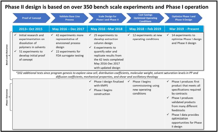
Source: The Company.
PureCycle Ohio Facility
Independent Engineer’s Report
Page 23
Bench-Scale Testing Background
The Company conducted a series of bench-scale tests at an independent laboratory to develop, assess, and verify the polypropylene recycle concept and the key process steps. The key steps of the PCT Technology that were investigated in these bench-scale experiments were: (1) extraction of solvent-soluble (and odor-causing) contaminants; (2) dissolution of polypropylene in the solvent; (3) settling of insoluble (e.g., polymer and color pigment) contaminants/decanting of soluble phase; and (4) filtration/adsorption of insoluble contaminants. The extraction step involves operation under conditions where the polypropylene and solvent exist in two distinct liquid phases. The dissolution, settling, filtration, and adsorption steps involve operation under conditions where the polypropylene is dissolved in the solvent to form one homogeneous liquid phase.
The intent of the initial bench-scale tests was to explore the effects of a number of key process variables and components in order to converge on an optimized system design. Later tests were focused primarily on addressing/resolving specific issues associated with assessing the applicability of the bench-scale system components and results to the design and operation of a commercial-scale system. The most recent tests were performed to explore operation under a second set of operating conditions than initially established that will generate similar quality product but at reduced capital expense and operating cost. It should be noted that the Phase I has only run at the second set of operating conditions.
The bench-scale tests were preceded by some early confirmatory work by P&G on dissolution of polymers in solvents, and some initial tests in the laboratory of Professor Marc McHugh of Virginia Commonwealth University. Once begun, the bench-scale tests were performed in several distinct series. An initial set of 51 tests was performed between April 2014 and October 2015. After P&G licensed the technology to Innventure, a second set of 42 tests was performed between May 2016 and June 2017. An additional set of 22 tests was performed between June and December 2017. This latter set included tests to measure the effectiveness of the lab system to extract U.S. Food and Drug Administration (“FDA”) specified surrogate contaminants spiked on polypropylene feed. A separate set of 25 experiments was performed during the same time period to measure distribution coefficients of these surrogates between the solvent at the proposed operating conditions and polypropylene phases. The collective surrogate test data were then used to help design the extraction column for the Phase II Facility. A specific set of six replicate tests was performed in February and March 2018 under the intended operating conditions and configuration intended for commercial-scale operation at the time to verify reproducibility of results and to quantify the odor of the final polypropylene product by a professional odor assessment expert.
All of the above described tests were performed under a constant nominal temperature with pressure being the variable adjusted to transition from the two phase (with respect to polypropylene and solvent) extraction conditions to the single phase dissolution/settling/filtration conditions. In an effort to reduce cost, the Company conducted a total of 12 additional tests at the independent laboratory between May 2018 and February 2019. These tests were conducted at a new set of temperature and pressure operating conditions where pressure is held constant and temperature is adjusted to transition from the two-phase extraction conditions to the single-phase dissolution/settling/filtration conditions. The impact of polyethylene content in the feed on process performance and antioxidant addition to the feed on product specifications were also explored. The current process design is based on the results of these 12 most recent laboratory tests and Phase I performance data. The results of these tests run at the bench scale using the new operating conditions showed that the process can generate recycled polypropylene product that meets its key parameter targets on average, though not within the 95 percent confidence level of uncertainty for one parameter (color) due to the level of variance observed in the data. However, the larger size and expanded data set for the Phase I shows that its recycled polypropylene product also meets its key parameter targets on average. Phase I average values for color and opacity parameters were within the 95 percent confidence level of uncertainty, but not all Yellowness Index (“YI”) values met this because of a couple of known process issues that were corrected and the YI improved back to specification (more details provided in the Phase I Product Quality section below). While some product produced may be considered off specification material, this is typical of even commercial virgin polypropylene production facilities.
PureCycle Ohio Facility
Independent Engineer’s Report
Page 24
Key Product Quality Parameters
The Sponsor has identified the following four properties as being key to assessing the quality of the recycled polypropylene and therefore the effectiveness of the proposed recycle process: (1) color; (2) opacity; (3) Melt Flow Index (“MFI”); and (4) odor. Only the first three are included in product specifications and were assessed throughout all bench-scale tests performed. While odor is not an official product specification in the offtake contracts, product with an odor quality comparable to that of virgin polypropylene may result in a higher selling price or a broader market in which to sell. It should be noted that there is no industry accepted standard test to quantify odor. The data supporting the product quality is detailed in below sections.
The color properties were measured according to the International Commission on Illumination (“CIE”) color scale parameters “L*”, “a*”, and “b*” (“CIELAB”). In the CIELAB color scale, L* is the lightness value (L*=0 is black and L*=100 is white), a* is the green-red color component (positive a* is red and negative a* is green, and b* is the blue-yellow component (positive b* is yellow and negative b* is blue). Of these three parameters, the b* value is the most important for this application, as it expresses the blue-yellow component of color and yellowness is an undesirable property of the preferred white recycled polypropylene product.
Values for L*, a*, b*, opacity, and MFI were measured starting with the second set of bench-scale tests performed beginning in May 2016. All analyses were performed by staff contracted by the Company on product fractions shipped to them from the testing laboratory. The measured values for these parameters determined for each test were used to assess the overall success of each test and guide the direction of future tests. The ideal target specification for the b* value is 2.5, which is equivalent to that of virgin polypropylene. The Company has stated that a b* value up to 5 is still acceptable for some applications and a value of less than or equal to 5 is the Company’s target.
The UPRP offtake agreements have yellowness specifications for b*, as well as a second yellowness parameter, YI. The UPRP offtake agreements do not have specifications for L* or a*. The determination of all colorimetric parameter values, including YI, is made via spectrophotometric analysis in accordance with the American Society for Testing and Materials (“ASTM”) ASTM D6290 and ASTM E313. ASTM D6290 requires the analyzed sample to be in pellet form. During bench-scale testing, insufficient quantities of recycled polypropylene product for pellet formation were generated in each test. As a result, smaller 1 mm flat panel shaped samples were prepared from each bench-scale test product for analysis via a Company-modified version of ASTM D4703. These flat samples were then analyzed by spectrophotometer to determine values for b*. In order to convert these b* values to equivalent YI values for pellets for comparison to the limit in the offtake agreements, the Sponsor developed an empirical linear equation between YI (for pellets) and b* (for 1 mm panels) based on measurements performed on both virgin polypropylene and on recycled polypropylene product combined from multiple bench-scale tests. The empirical equation provided by the Sponsor is as follows:
YI = 6 b* -10
Thus the target values for b* for recycled polypropylene of less than 2.5 (ideal) and less than 5 (acceptable) in terms of YI become less than 5 and 20, respectively. This empirical equation also allows one to translate and compare b* data from the bench-scale tests discussed below to product contract guarantee values stated in terms of YI. The YI specification in the UPRP offtake agreements is a maximum of 20.
PureCycle Ohio Facility
Independent Engineer’s Report
Page 25
Opacity (“Y”) also can impact the color of the recycled polypropylene product. The Company’s target specification for opacity is less than or equal to 20 percent.
The MFI specification, measured in units of grams per 10 minutes (“g/10 min”), is not as stringent as the others and can range between 10 and 55, depending on the MFI of the feedstock, the particular customer’s preferences, and intended application of the polypropylene.
Of the four quality parameters, odor was the most difficult to characterize and measure. The ideal target with respect to odor is for the recycled polypropylene product to be comparable to that associated with virgin polypropylene. The Company reports that Industry experts have been unsuccessful to date in identifying and quantifying the chemical species responsible for odor that need to be removed from the recycled polypropylene. As a result, the Company has relied on a combination of the test results (confirmed by a professional odor grader) and quantitative data measured for surrogate compounds to address this issue. The Company stated that odor is not a concern for some potential recycled polypropylene product customers and the Company does not specify odor as a specification of its product. However, it would be desirable to demonstrate that the process can generate product that will significantly reduce the odor of the feedstock and potentially be comparable or nearly comparable to virgin polypropylene with respect to odor to increase product value.
Test Procedures
A typical bench-scale test demonstrating the complete process took three days and used two distinct equipment configurations. The test set up did not have the capability of performing the entire process at the same time. The first configuration performed the extraction step and the second configuration performed the dissolution, settling, filtration and adsorption steps. Note that not every bench-scale test performed was intended to demonstrate the full process, as many tests were focused on only a specific step such as filtration or adsorption and were therefore of shorter duration. Also, the majority of previous tests were performed under a different pressure-temperature operating approach and a different equipment configuration than the more recent tests, in each case to achieve the same conditions necessary for the main steps in the process. The process description below is based on the conditions and configuration used in the more recent tests, which most closely represents the current intended operating approach at the Phase II Facility and the operating conditions demonstrated with Phase I.
Consistent with the Phase II Facility process flow, the extraction step was performed first. The purpose of the extraction step is to remove soluble and odorous contaminants in the polypropylene feed material using solvent at certain operating conditions. In the Phase II Facility, this step is performed in the extraction column. The reactor setup consisted of a 2-gallon stirred tank reactor manufactured by the Parr Instrument Co (the “Parr Reactor”). After loading feedstock into the reactor, air was removed from the headspace via several cycles of vacuum and nitrogen purge before adding solvent and initiating pressurization and heat-up. For the extraction step, solvent entered the Parr Reactor near the bottom via a dip-tube from a top port and flowed out of the reactor from a separate top port, mimicking the direction of flow and polypropylene contact intended in the Phase II Facility extraction column. Several cycles (typically five) of reactor stirring, settling, and solvent flow for a time equivalent to replacing one reactor volume were repeated as part of the extraction step. Each cycle yielded a sample of extracted solids.
PureCycle Ohio Facility
Independent Engineer’s Report
Page 26
After the extraction portion of the test was completed, the reactor was isolated and the temperature set point reduced while the system was reconfigured for the dissolution, settling, filtration, and adsorption part of the test. The purpose of this dissolution/filtration step is to remove color pigments, other polymers, and other insoluble solids from polypropylene under conditions where the polypropylene is now soluble in the solvent. For this part, the solvent flow into the reactor was reversed relative to extraction (i.e., in through the top and out through the dip tube at the bottom). The temperature was reduced at the same system pressure to a value where polypropylene is soluble. After passing through the settling, filtration, and adsorption steps, the purified solution was reheated to the extraction temperature and passed through a cylinder representing a product decanter. The polypropylene product and solvent were separated in the decanter and all polypropylene product was recovered for measurement.
Bench-Scale Tests Performed
Initial Tests
The company reports that more than 350 tests were conducted at the bench-scale, however we reviewed only a total of 133 bench scale tests to represent all or part of the PCT Technology. These bench-scale tests were performed in several distinct series. The first 121 tests were performed under constant temperature with pressure being increased to go from extraction to filtration conditions. Of these, an initial set of 51 tests was performed between April 2014 and October 2015. These first tests appear to be focused mainly on proof of concept and are not considered by the Company to be representative of the current process design.
The next set of 42 tests was performed between May 2016 and June 2017. These tests (for which more detailed data was provided to Leidos in summary form) were considered by the Company to be more representative of the Phase II Facility process, but at different temperature and pressure operating conditions than is currently proposed for use. All of the tests in this set were performed in the system described in the previous section on typical test procedures, with equipment consisting of the 2-gallon capacity Parr Reactor followed by the filter and/or one or more adsorption columns but no product decanter.
The 42 tests of this set focused on identifying the impact of a number of key variables on process operating conditions and overall product quality. However, not all variables were tested at the same time. The following variables were investigated:
| · | Polypropylene feed type (e.g., mixed color Jazz flakes, virgin polypropylene, dirty diapers, agricultural bags); |
| · | Polypropylene feed quantity; |
| · | Polypropylene feed additive and quantity (for tests performed with virgin polypropylene); |
| · | Reactor stirring speed (for both extraction and dissolution); |
| · | Settling time (for both extraction and dissolution); |
| · | Total displacement time (for both extraction and dissolution); |
| · | Displacement fluid type; |
| · | Number of solvent flush cycles (for both extraction and filtration); |
| · | Filter filtration area (10 percent or 100 percent); |
| · | Adsorbent material type and properties; and |
| · | Number of adsorption columns (e.g., 0-3). |
Test No. 42 was the first to demonstrate the complete process of extraction, followed by filtration through the filter and an adsorption column.
PureCycle Ohio Facility
Independent Engineer’s Report
Page 27
FDA Surrogate Tests
In terms of equipment, the extraction step is the most different when comparing that used in the bench-scale tests with that designed for Phase I and the Phase II Facility. The extraction step is also the point in the process where odor causing compounds are removed. To provide design information for the Phase II Facility extraction column, the Company performed a series of bench-scale tests after Test No. 42 with polypropylene feed spiked with several FDA recommended surrogate compounds. The compounds represent different extremes in volatility and polarity as discussed in the FDA document titled “Guidance for Industry: Use of Recycled Plastics in Food Packaging (Chemistry Considerations,” August 2006 (the “FDA Guidelines”). While the FDA Guidelines are intended to estimate the maximum contaminant concentration in recycled plastic used for food storage, the Company believes that it is applicable to estimating residual amounts of odor causing compounds in recycled polypropylene as well. According to the FDA Guidelines, this concentration is dependent only on the nature of the plastic. For polyolefins (such as polypropylene), the maximum safe contaminant concentration to meet in the recycling process is 320 parts per billion (“ppb”).
The FDA surrogate tests were performed between June and December 2017 (No. 43-64), which included several with polypropylene feed spiked with one of several different surrogate contaminant compounds. The product fractions from these tests were analyzed for the surrogate by the Company. The surrogate that was the hardest to remove in these tests was benzophenone (“BP”), which represents an extreme for non-volatile, polar compounds. BP concentrations ranged from 800 to 4,300 ppb over several product fractions in these tests. The argument that BP is the hardest surrogate to remove from the polypropylene is supported by a set of alternate experiments that were performed to determine the distribution coefficient (“DC”) of each surrogate between the solvent phase and polypropylene phase under extraction conditions. BP had the lowest calculated DC at 1.1, indicating that the BP only slightly prefers the extract phase and should thus be the hardest to extract from the polypropylene.
Based on the results of the bench-scale tests with surrogates, the Company concluded that BP represents the most difficult compound to extract from polypropylene feed. As a result, KMPS designed the Phase II Facility extraction column to achieve a final concentration of 320 ppb of BP in the polypropylene phase leaving the column. The Company believes that a design based on BP removal will be sufficient to ensure removal of all odor causing contaminants by the following reasoning. A design of 320 ppb BP is well below the concentration of several thousand ppb of BP measured in the polypropylene product from the surrogate tests. On the same bench-scale system run under the same conditions, the Company reported that the majority of bench-scale tests previously generated polypropylene product with no detectable odor (qualitatively). Therefore, the Company believes that a 320 ppb design for BP should be sufficient with margin to also ensure removal of all odor contaminants, without needing to know the identities or amounts of each individual odor contaminant.
The Company and KMPS believe that the surrogate approach is applicable to providing a basis for the design of the extraction column, because they believe that the proposed surrogates (BP in particular) are valid representatives of odor causing compounds that have an affinity for plastics (note that all of the odor contaminants of concern by definition need to have an affinity for polypropylene or they would not be on the polypropylene feed to begin with). With BP being nonvolatile, there is a reasoning that this compound should be harder to extract from the polypropylene phase than odor contaminants which by their nature are volatile and thus more likely to leave the polypropylene phase than a non-volatile substance. However, the argument of using this approach hinges on the following assumptions: (1) whether BP is the most conservative representative of the behavior of odor contaminants, even within the subset of those with an affinity for polypropylene; (2) whether the Phase II Facility extraction column can duplicate the bench-scale system results; and (3) whether the odor contaminants of concern are sufficiently similar to BP to behave in a linear way to changes (e.g., a change that results in a reduction in BP concentration results in a comparable reduction in odor contaminant concentration). We note that, based on this testing, KMPS in the equipment supply contract is guaranteeing an odor removal level of 2.5 odor units (1.0 units above the typical value for virgin polypropylene) or less.
PureCycle Ohio Facility
Independent Engineer’s Report
Page 28
Replicate Tests
After review of the test results and approach outlined above in January 2018, it was determined that an additional set of six bench-scale tests (No. 65-70) should be performed. These tests were intended to be replicate tests performed under the chosen conditions (at that time) and with components intended for use at pilot and commercial-scale plants based on the results of all of the previous bench-scale tests. Thus, these tests were intended to address the reproducibility and reliability of results, which had not previously been demonstrated. The six tests were performed between February and March 2018. All were performed at the approximate conditions of temperature of [*****] with the extraction step at [*****] psig and the dissolution/settling/filtration/ adsorption step at [*****] psig.
Most Recent Tests are New (Refined) Process Conditions
As part of an effort to reduce capital and operating costs for the Phase II Facility process, the Company performed a series of bench-scale tests at the independent laboratory to explore several different process changes. These changes included: (1) a new set of temperature and pressure operating conditions; (2) elimination of anti-oxidant addition to the feedstock; and (3) the effect of polyethylene composition of the feedstock on filtration performance. The additional tests (#79-110) were performed between May 2018 and February 2019. Of these, a total of 12 tests were considered sufficiently relevant to the above three issues with data provided to Leidos for review. There is overlap in these tests in that many explore more than one of these above issues at the same time and utilize different feedstocks. Thus, there are no true replicates in this set, although changes in variables associated with one issue do not appear to have had a direct impact on parameters or specifications associated with the other issues. According to the Company, the other tests in this series for which data were not provided to Leidos focused on developing a better fundamental understanding of the other parameters in the process (e.g., dynamic settling kinetics and behavior).
As stated earlier, the process is designed so that the extraction step in the process is performed under conditions where the polypropylene and solvent exist in two distinct liquid phases and the subsequent dissolution/settling/filtration/adsorption step is performed under conditions where the polypropylene is dissolved in the solvent in a single liquid phase. Through previous testing, the Company has developed a phase diagram for the two component system of polypropylene and solvent, with polypropylene at [*****] percent (representative of the Phase II Facility process design). It has also identified areas in the two phase and single phase regions on the phase diagram where the extraction and filtration steps of the process should be able to occur (Figure 6). Previous bench-scale tests had been performed at a constant temperature with adjustment of pressure to move between the two process steps due to the ease of operating this way with the bench-scale equipment. However, operation at lower pressure at the Phase II Facility should reduce equipment costs. As a result, tests were performed to identify a single, lower operating pressure with temperature adjustment to transition between the two process steps that would still generate acceptable product under stable process conditions. Of the 12 tests identified where data was provided, all but one were performed at the approximate conditions of an operating pressure of [*****] psig with a temperature of [*****] for the extraction step and a temperature of [*****] for the subsequent dissolution/settling/filtration/adsorption step. Phase I has been operating at these approximate conditions and the Phase II Facility design has also been updated to reflect these approximate operating conditions.
PureCycle Ohio Facility
Independent Engineer’s
Report
Page 29
Figure 6: Phase Diagram of Polypropylene/Solvent Binary System
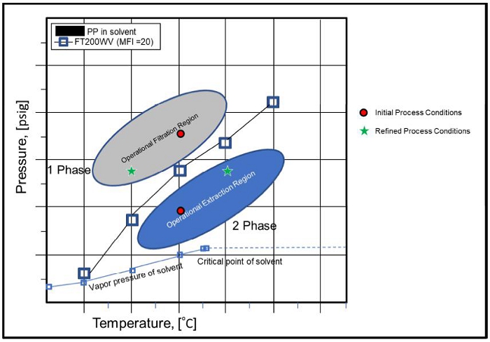
Source: The Company.
Antioxidant had previously been added to the feed because earlier tests were thought to show that this chemical eliminated increases in MFI values of product relative to the feedstock. However, subsequent tests with antioxidant continued to exhibit these unwanted increases in product MFI values. It was discovered that the laboratory procedures did not explicitly require removal of air from the reactor prior to starting a test. These most recent tests explored the effect of antioxidant addition to the feed and inclusion of a combination of nitrogen purge and vacuum to remove air from the reactor prior to introducing solvent flow. The Company reports that Phase I operation has confirmed these findings and resulted in slight modifications to the Phase II Facility design.
Previous tests suggested that the presence of higher concentrations of polyethylene (itself an impurity to be removed) in the feedstock led to better overall settling of impurities and reduced subsequent buildup on the downstream filter element. To more formally test this observation in a controlled manner, several of the most recent tests were performed with and without polyethylene added to the feedstock at a concentration of 5 percent
Bench-scale Testing Results and Evaluation
Of the most recent bench-scale tests performed, the 12 for which data were provided most closely represent the Company’s operating conditions intended for commercial-scale and thus are most relevant to evaluate regarding the proposed process and its capabilities. While there is less data at the bench scale level of the current intended operating conditions than there were at the former operating conditions, data from Phase I operation (which is discussed in sections below) utilizes the current intended operating conditions planned for the Phase II Facility design. When considering the operating pressure and temperature, addition of antioxidant and system purge, and addition of polyethylene issues together, none of the 12 tests are true replicates. However, when focusing on any one of these issues alone, several tests could be considered replicates. Six of the tests were performed at the approximate target conditions of [*****] psig and [*****] and [*****] (four of these with the same type of feedstock type). Three of the tests were performed without anti-oxidant and a system purge to remove air (none of these with the same feedstock type). Five tests were performed with [*****] percent feed spike of polyethylene (three having the same feedstock type).
PureCycle Ohio Facility
Independent Engineer’s Report
Page 30
The change in process approximate pressure-temperature operating conditions of [*****] psig for extraction and [*****] psig for filtration to the approximately operating conditions of [*****] psig for extraction and [*****] psig for filtration is significant from a process operation standpoint. However, as long as one resides in the proper regions of the phase diagram for which each step in the process was designed (i.e., two liquid phases for extraction and a single liquid phase for filtration with respect to polypropylene and solvent), there should not be any change in the purified product amount or specifications, in theory. We are aware of independent studies published in the literature of the same polypropylene-solvent system that support the phase boundary curves shown in Figure 6. The specific regions on the phase diagram that are acceptable for the extraction and filtration steps (shown in Figure 6 as oval shaded regions) and their boundaries are less certain and identified only by the Company based on its research. As can be seen in Figure 6, both former (initial) and current (refined) operating points lie within the appropriate oval regions. Analysis of sample data allows assessment of how well the new or refined conditions can produce product of comparable quality and quantity as was seen in tests performed under the initial conditions.
Values for the product specifications of color (b*) and opacity (Y) from the most recent tests performed at refined pressure and temperature operating conditions are shown in Table 1. Six of these tests were performed using three different types of waste polypropylene feedstock. Five tests were performed using virgin polypropylene as feedstock, which should function as a control since virgin polypropylene is the benchmark to which the recycled polypropylene is to match.
With respect to color quality (b*) results, values for refined condition tests ranged from 2.6 to 5.6. Values for b* from tests with virgin polypropylene feed were not necessarily better than that from tests with actual waste feedstock, showing a comparable range in magnitude and slightly higher variance (the Company has also noticed this observation but does not have an explanation). Only one out of the 11 data points were at or above the Company’s target value of 5 and all values from tests with waste feedstock were below 5. The average b* value over all eleven tests was 3.6 plus or minus 2.0, where the uncertainty represents the 95 percent confidence interval. Note that the upper range of uncertainty (5.6) is above the Company’s target value of 5. Thus it would appear that based on this relatively limited sample size, operation at the refined process conditions is capable of generating product of comparable color quality as produced under the initial process conditions. KMPS has provided a process guarantee for YI of less than 20 which is equivalent to a b* value of less than 5.0.
With respect to opacity results, values ranged from 8.6 percent to 19.7 percent, with all but one data point between 8.6 and 14 percent (the Company believes that the 19.7 percent analysis from test No. 100 may have been affected by bubbles in the sample caused by residual solvent). As with color quality results, opacity results from tests with virgin polypropylene feed were not much different from those from tests with real waste feedstock. The average value over all eleven tests was 10.9 plus or minus 6.6 percent, where the uncertainty represents the 95 percent confidence interval. This average is well below the Company’s target value of 20 percent even considering the data spread and uncertainty range. KMPS has provided a process guarantee of 20 percent or less.
PureCycle Ohio Facility
Independent Engineer’s Report
Page 31
Table 1
Bench-Scale Product Specifications Average Test Results (1)
| Test Number | Feed Type | Color (b*) | Opacity (Y) Percent | |||||||
| 100 | Jazz Flake | 3.3 | 19.7 | |||||||
| 101 | Herbold Carpet Fiber | 3.2 | 9.7 | |||||||
| 106 | Herbold Carpet Fiber | 4.8 | 9.5 | |||||||
| 107 | Herbold Carpet Fiber | 3.0 | 8.6 | |||||||
| 110 | Herbold Carpet Fiber | 4.1 | 9.4 | |||||||
| 109 | Stadium Trash | 2.6 | 10.8 | |||||||
| 98 | Virgin Polypropylene | 5.6 | 14 | |||||||
| 102 | Virgin Polypropylene | 4.6 | 11 | |||||||
| 104 | Virgin Polypropylene | 2.6 | 9.1 | |||||||
| 105 | Virgin Polypropylene | 3.6 | 9.4 | |||||||
| 108 | Virgin Polypropylene | 2.7 | 9.2 | |||||||
| Overall Average | 3.6 | 10.9 | ||||||||
| Standard Sample Deviation | 1.0 | 3.3 | ||||||||
| 95 Percent Confidence Interval | 2.0 | 6.6 | ||||||||
1) Operating conditions: approximately [*****] (extraction), [*****] (filtration).
Overall, it would appear that based on this relatively limited sample size of bench-scale data, operation at the refined process conditions is capable of generating product of comparable quality to that produced under the initial process conditions and capable of meeting color and opacity specifications in the product sales contracts. However, the variance exhibited in the color and opacity values measured was consistently higher than one would expect and could lead to wider variations in color (in some cases exceeding specifications) and opacity than desired. The tests performed under refined process conditions also had lower mass balance closure compared to the larger number of tests performed under initial conditions. The larger sample size of data to date from Phase I supports this view, confirming the capability of generating acceptable quality product although with comparable levels of variance in key parameters. The Company believes that this is due to the additional experimental equipment (e.g., product decanter) and piping used in the most recent test set-up and additional polymer residue in this equipment and piping that was not recovered. Operation of the Phase I to date has provided comparable results to these bench-scale tests with respect to product quality (see Phase I Operation section below).
In terms of product quantity recovered, Table 2 shows the amount of polypropylene recovered in the first of the five extractions during the extraction step. Only the first extract is considered for this analysis because it is the closest that the bench-scale system comes to mimicking the Phase II Facility extraction column performance before the continued solvent flow to the batch reactor inevitably dilutes the contents in later extraction steps. Ideally, one would like the polypropylene found in the extraction step to be low as possible (up to the solubility limit) and the polypropylene product recovered after filtration to be as high as possible. A comparison of the extract concentration of polypropylene under the refined conditions shown in Table 2 to those values observed in the previous tests under the initial conditions shows no significant difference in these values, apart from a somewhat wider range of variability over the refined conditions values, which could be related to the fewer number of tests performed to date. A notable exception is test No. 104 where the combined relatively high concentration in the extract indicates a higher loss of polypropylene (the likely reason for this is explained below). Overall, however, the results suggest that operation at the refined conditions should be equally viable relative to product recovery and loss compared to the initial conditions, provided that the designated pressure and temperature setpoints for each process step can be maintained.
PureCycle Ohio Facility
Independent Engineer’s Report
Page 32
Table 2
Bench-Scale Product Quantity Results (1)
| Test Number | Feed Type | Polypropylene Concentration In First Solvent Extract(%)(2) | ||||
| 100 | Jazz Flake | [*****] | ||||
| 101 | Herbold Carpet Fiber | [*****] | ||||
| 106 | Herbold Carpet Fiber | [*****] | ||||
| 107 | Herbold Carpet Fiber | [*****] | ||||
| 110 | Herbold Carpet Fiber | [*****] | ||||
| 109 | Stadium Trash | [*****] | ||||
| 98 | Virgin Polypropylene | [*****] | ||||
| 102 | Virgin Polypropylene | [*****] | ||||
| 104 | Virgin Polypropylene | [*****] | ||||
| 105 | Virgin Polypropylene | [*****] | ||||
| 108 | Virgin Polypropylene | [*****] | ||||
1) Operating conditions: approximately [*****] (extraction), [*****] (filtration).
2) Based on mass of polypropylene fed to reactor.
Meeting product specifications in the most recent tests supports the concept of being able to operate successfully at more than one set of process conditions provided that the extraction and filtration steps are performed under conditions within the appropriate oval regions identified on the phase diagram for the system (Figure 6). The impact of migrating to the wrong operating conditions was demonstrated in one of the recent lab tests (No. 104), where pressure during the extraction step unintentionally rose to a value close to the phase boundary curve (approximately [*****]). This test exhibited a notably greater amount of solid material removed in the extraction step, likely the undesired result of more polypropylene dissolving in the solvent because of moving closer to single phase conditions. The net result is a loss of potential polypropylene product. Having a single phase present during the extraction step or having two phases present during the filtration step would both result in the same effect of losing polypropylene product to a waste stream and consequently lost revenue. The Company reports that operation of Phase I has allowed it to ‘tune” the control methodology to maintain operations within the proper conditions.
Table 3 shows the lab test results of feed anti-oxidant addition impact on product MFI values. Data from earlier bench-scale tests showed an undesirable increase in MFI in the product relative to the feedstock. As seen in data in the top half of Table 3, the Company anticipated that addition of anti-oxidant was necessary to prevent the increase in product MFI (oxygen can shorten polymer chains and break crosslinks, resulting in an overall lower viscosity and thus a high MFI value). At some point, the Company discovered that the laboratory performing the bench-scale tests did not include a step in their standard operating procedures to actively remove air from the experimental setup before introducing solvent. Upon implementing a nitrogen and vacuum purge, the data indicates that removal of air from the system is sufficient to prevent the variable increase in product MFI, as shown in the bottom half of Table 3. The Company reports that these changes have been made at Phase I. Anti-oxidant removal by the Company for the Phase II Facility process design (at the feedstock end) is supported by the most recent test data. The data also show that the process should be capable of meeting the Company’s target range for product MFI of 10-55 g/10 min. Elimination of antioxidant addition to the feedstock would save on operating costs at commercial-scale. KMPS is not guaranteeing a level of MFI or a change from the initial material.
PureCycle Ohio Facility
Independent Engineer’s Report
Page 33
Table 3
Bench-Scale Anti-Oxidant Effect Test Results
| Test Number | Feed Type | Feed Anti- Oxidant (Yes/No) | Reactor purge (Yes/No) | Feed MFI (g/10 min) | Product MFI (g/10 min) | |||||||||||
| 79 | Jazz flake | Yes | No | 20.0 | 25.0 | |||||||||||
| 102 | Virgin polypropylene | Yes | No | 23.2 | 20.8 | |||||||||||
| 98 | Virgin polypropylene | No | No | 23.2 | 56.4 | |||||||||||
| 100 | Jazz flake | No | No | 20.0 | 64.0 | |||||||||||
| 101 | Herbold carpet fiber | No | No | 14.5 | 43.7 | |||||||||||
| 104 | Virgin polypropylene | No | No | 23.2 | 41.1 | |||||||||||
| 105 | Virgin polypropylene | Yes | Yes | 23.2 | 14.2 | |||||||||||
| 106 | Herbold carpet fiber | Yes | Yes | 14.5 | 11.3 | |||||||||||
| 107 | Herbold carpet fiber | No | Yes | 14.5 | 11.5 | |||||||||||
| 108 | Virgin polypropylene | No | Yes | 23.2 | 12.7 | |||||||||||
| 109 | Stadium trash | No | Yes | 6.3 | 5.1 | |||||||||||
| 110 | Herbold carpet fiber | No | Yes | 14.5 | 8.7 | |||||||||||
Over the course of bench-scale testing, the Company noticed that tests performed with feedstock containing a higher amount of polyethylene impurity exhibited better removal of all solid impurities during the settling, filtration, and adsorption step. In the bench-scale test equipment, this manifests itself by a larger amount of residual solids recovered from the bottom of the reactor at the end of the test, a smaller amount of solid buildup on the candle filter element, and a smaller gain in mass of the adsorption column material. To more formally examine this observation in a controlled manner, several of the more recent tests were performed with carpet fiber feedstock. The carpet fiber is a polypropylene material that does not contain polyethylene. This feedstock was spiked in three tests with [*****] percent polyethylene, while one test was performed with no spike as a control. The data reviewed show a clear, though relatively small, increase in the reactor residual solids and decrease in the candle filter and adsorption column mass. This result implies that more solid impurity settles to the bottom of the reactor in the presence of polyethylene, reducing the load on the downstream candle filter and adsorption column. Though only a small number of tests were performed, the results appear to support the concept that polyethylene aids in settling. While the mechanism by which polyethylene helps remove solids is not clear, its impact at the Phase II Facility could be significant by reducing the frequency at which the candle filter elements need to be cleaned and adsorption column material needs to be replaced. Polyethylene addition to the feed is currently being used in Phase I operation. The Company reports that the Phase I has functioned well at polyethylene concentrations up to its design target value of [*****] weight percent. However, Phase I operation at high polyethylene levels in the feed ([*****] weight percent) results in plugging of the extraction and mixing columns. Thus, the limited current data suggest that there may be a limit to the beneficial effects of polyethylene concentration, which would need to be controlled or managed. The company reports that a non-stick coating will be added to the extraction column and all downstream units up through the polyethylene settler in the Phase II Facility design to aid in avoiding this problem. Current information suggests that this coating will aid in the removal of polyethylene, preventing the adherence to the metal surfaces. The Company states that the Phase II Facility will also manage the polyethylene amount to ensure optimum removal.
Differences between Bench-Scale Tests and the Proposed Phase II Facility (Commercial-Scale) Process
The bench-scale tests were intended to define and prove out the basic steps of the recycle process: extraction, dissolution, settling, and filtration/adsorption. However, because of the small-scale of the test equipment, there are inevitable differences when moving to both pilot-scale (Phase I) scale and commercial-scale (Phase II Facility) versions of the process.
PureCycle Ohio Facility
Independent Engineer’s Report
Page 34
The most significant difference between the bench-scale equipment and that proposed for the Phase II Facility is with the extraction step. In the bench-scale tests, a batch stirred autoclave with a single impeller was used for the solvent to contact and extract soluble odor-causing impurities from the polypropylene molten phase. After the pre-determined time for mixing and contact, a fresh flow of solvent was injected into the reactor to force out the existing impurity-laden solvent (along with some soluble polypropylene). This cycle was repeated several times (typically five, although the Company reported that as little as two are needed) to achieve the intended extraction of soluble impurities. The equipment intended to achieve the extraction step in the proposed Facility II Facility is an extraction column, which functions differently from a batch autoclave reactor. The extraction column is a common process unit operation used for liquid – liquid extraction. The vertical extraction column contains a number of stages and operates in a continuous mode, where a feed solution of molten polypropylene and solvent flows countercurrent to a stream of pure solvent. Each stage contains an impeller between horizontal baffles. The impeller is connected to a common central rotating shaft. Here, mass transfer of impurities from the polypropylene to pure solvent phase is continuous, with the amount extracted dependent on the effectiveness of contact and mixing achieved at each stage as well as the concentration (equilibrium) driving force. The correlation of the number of stages in the extraction column to the five extractive flushes used in the batch autoclave tests is not fully understood. KMPS has designed the Phase II extraction column based on the results of the BP testing and the determination of the distribution coefficient. Based on that analysis, KMPS has stated that is intends to incorporate 65 stages in the column, which has allowed KMPS to provide the process guarantees. If necessary, a second column could be incorporated into the Phase II process to increase the residence time for the extraction. Operation of Phase I is intended to provide data that will help confirm the design of the Phase II extraction column. See the next section below for further discussion with respect to data provided from initial Phase I operation.
There are also differences between the bench-scale tests and Phase II Facility process for the dissolution and settling steps, though not as pronounced as in the extraction step. In the bench-scale system, extraction, dissolution, and settling were all performed in the same batch reactor, just under different operating conditions for each step. Additional tests were conducted outside of the primary bench-scale equipment to address dissolution and settling which could not be readily observed in the primary equipment. A series of dissolution tests were performed in a high-pressure cell with visual access showed polypropylene mixing times at the approximate operating conditions of [*****] psi and [*****] to be on the order of 60 seconds. These tests were later repeated at the approximate conditions of [*****] psig and [*****] and showed dissolution times on the order of 10-15 seconds. Dissolution may be aided in the Phase II Facility system by the use of a mixing column. Preliminary data from the mixing column in Phase I indicates a longer mixing time than originally intended but with no apparent negative impact on downstream equipment performance or product quality. To confirm settling times, separate tests were performed in a Jerguson gage cell specifically to investigate settling times of heavier particles that are directly applicable in the design and size of the Phase II Facility decanter. At the approximate conditions of [*****] psig and [*****] the test data indicated a time of about 2.5 minutes for settling of polyethylene, the main contaminant to be removed in the decanter. A similar test performed at approximately [*****] psig and [*****] showed the same settling velocities and settling time on the order of 2-3 minutes. The Company reports that later tests at an independent facility (the “Test Facility”) indicated that a longer settling time would be needed. The settling time cannot be validated in Phase I because the decanter being used is not representative of the Phase II Facility design. However, KMPS is guaranteeing the performance of the ISBL, which includes the decanter.
PureCycle Ohio Facility
Independent Engineer’s Report
Page 35
The bench-scale tests are most consistent with the proposed Phase II Facility process in the filtration/adsorption step. The use of a filter followed by adsorption column in series as arranged in the more recent bench-scale tests is similar to that intended for the Phase II Facility process, differing only in size and number. A single filter was used in the bench-scale tests followed by up to three adsorption columns. This has provided sufficient information for the Phase II Facility design. Although the Phase II Facility is to be designed with the two adsorption columns, the Company has not decided at the present time whether any adsorption columns will be needed during operation. Current data from Phase I operation suggests that one column will be needed for at least some feed types. If all specifications in the final product can be met by these upstream operations, no adsorption step will be necessary.
Phase I Operation
Phase I is a large pilot-scale facility for testing the PCT Technology. It was built on the same Facility Site as the Phase II Facility is to be constructed on. Phase I consists of a fully integrated version of the PCT Technology that is representative of the process and equipment intended for the Phase II Facility (with some exceptions as noted below). The process is continuous up to the product decanter, which includes all of the unit operations intended for impurity removal. As a result of the feed flow rate being too low in Phase I to maintain adequate die pressure to properly operate the polymer (product) extruder, the process must be run in batch mode downstream of the product decanter. Polypropylene product is accumulated during continuous operation of the process upstream of the product decanter. When a sufficient quantity of polypropylene has been produced, the polypropylene “batch” is sent downstream through the product extruder while the upstream process is placed in idle (all units operating with solvent flow but no feed being processed). The batch operation of the downstream portion of the process is not consistent with the fully continuous Phase II Facility design. However, it does not change the capability of Phase I to produce relevant data. The Company considers the primary objective of the Phase I to explore process operations with individual supplier materials of different feedstocks, as opposed to the more continuous and consistent feed operation expected at the Phase II Facility.
The purpose of the Phase I is to: (1) verify system performance and key process parameters identified from bench-scale testing, and (2) provide a means of testing various polypropylene feedstock types supplied by potential customers or strategic partners and assessing the quantity and quality of recycled product generated. With regard to the latter point, the Phase I design incorporates certain items (e.g., electrical heat tracing) that cause operational problems with short-term runs (e.g., cold spots, loss of material during starts and stops). As a result, the Company states that throughput is not a goal in the Phase I, unlike the Phase II Facility production line. The Phase I was commissioned between February and June 2019 using virgin polypropylene feedstock and began operating on waste polypropylene feedstock on June 30, 2019.
Phase I Design
The Phase I physical equipment and layout is based on the 2017 version of the KMPS design (e.g., 50 stage isothermal extraction column, mixing of polypropylene and solvent prior to entering the extraction column rather than only polypropylene feed to the column, single feed extruder, ability to operate at approximately [*****] psig). However, the system is being operated according to the latest version of the design (e.g., fixed pressure with changing temperature to go from two phases for extraction to a single phase for filtration, polyethylene added to the feedstock, no anti-oxidant additive added to feedstock). To accommodate the current pressure-temperature operating scheme, recertification of the extraction column for the higher pressure was required.
PureCycle Ohio Facility
Independent Engineer’s Report
Page 36
In Phase I, feedstock that has already been size-reduced is fed to a single feed extruder. The molten polypropylene from the extruder is then combined with solvent (unlike in the Phase II Facility design) and sent to the countercurrent flow extraction column where it encounters a separate stream of pure solvent. The polypropylene/solvent mixture from the extraction column bottom is then sent to a mixing column, where more solvent is added and the temperature reduced for the polypropylene and solvent to form a single phase flow. The flow then enters a decanter vessel (settler) for removal of polyethylene/solids. The polyethylene decanter is a batch-run (with respect to solids removal; the polypropylene/solvent phase is continuous), vertical vessel that is not representative of the horizontal decanter with an auger for continuous removal of solids in the Phase II Facility design. Phase I must be shutdown periodically to empty the decanter of solids. After the decanter, the main flow enters one of two candle filters. The filtrate is sent to one of four adsorption columns (the Phase II Facility design has two). Despite the presence of multiple filters and adsorption columns, cleaning of one cannot take place while another is in operation as in the Phase II Facility design due to a lack of appropriate valving in the Phase I system. We note that the Phase II Facility design of the candle filters and adsorption columns is more automated than the Phase I version. After leaving the column, flow passes through a horizontal product decanter (which is representative of the Phase II Facility in design and orientation), followed by the product extruder and pelletizer. The Phase I pelletizer differs from the Phase II Facility pelletizer in that it creates a thin cylinder of product, which is cooled and cut into pellet-sized particles, whereas the Phase II Facility pelletizer will form spherical pellets underwater. Note also that the extruder and pelletizer are run periodically in batch mode apart from the continuous upstream part of the process, as discussed above.
Phase I Process Data
As of February 20, 2020 (note that all data cited below is for operation up to this date), Phase I had accumulated approximately 609 hours of operation on several types of waste polypropylene feedstock (Table 4). The first feed type to be run was waste carpet fiber, which was processed for a total of 98 hours. This was followed by recycled stadium trash feed type, which was run for a total of 153 hours. The longest continuous operation on feed to date (98 hours) was with stadium trash. The next feed was curbside waste plastic from the European Union (“EU household”), which was run for only two segments but a total time of 85 hours. The most recent run segments utilized recycled stadium trash, one for a short period in November 2019 for about 28 hours and the other for a longer period of 245 hours in February 2020. Overall, Phase I has processed about 3,161 total pounds of waste polypropylene feedstock, generating about 1,742 pounds of recycled polypropylene product. This represents a yield of about 55 percent, which is lower than that achieved in the Test Facility bench-scale tests (typically 60-70 percent in the extraction step). Of the three feedstock campaigns performed over this period of evaluation, the data in Table 4 show that yield has been steadily improving, from 32 percent during the carpet fiber campaign, 50 percent for the first stadium trash campaign, 58 percent for the EU household campaign, and 72 percent for the most recent stadium trash campaign. Note also that when considering just polypropylene inputs and outputs, the yields are slightly higher because feed processed values in Table 4 include everything fed to the system and product collected values do not include post die scrap material. While it is noted that these values are below the Phase II Facility target product yield of 90.1 percent, the continued improvement of the Phase I product yield over the short time period of available data is encouraging.
The reason for the low product yield data in Phase I relative to that targeted for the Phase II Facility is due primarily to (1) inherent limitations in the Phase I related to the smaller equipment size and exploratory nature of operation that restricts the maximum product yield, and (2) the learning curve and initial inefficiencies in operation of a new facility as staff become familiar with system operation and behavior. With regard to the first point, the Company has stated that losses at the inlet polymer melt filter and at the polymer product extruder are notably higher in Phase I compared to the Phase II Facility design. The smaller size and tolerances of the Phase I equipment require a finer mesh screen in the melt filter, leading to a higher loss of material there relative to the Phase II Facility. The loss at the Phase I melt filter is estimated by the Company to be 4 percent at best (and could be higher), relative to about 1 percent for the Phase II Facility. The more frequent starts and stops of the Phase I product extruder due to the batch operation of this equipment as described above also results in a greater loss of material there as scrap or transition material. This is a result of needing to remove all of the previous material in the extruder prior to producing the new material run. This transition material is a mix between the two batch runs. The loss at the Phase I product extruder is estimated by the Company to be 3 percent at best (and could be higher for shorter runs), relative to less than 1 percent for the Phase II Facility. Thus, assuming the same feed purity (93 percent) and other losses expected commercially, the Company estimates that the theoretical maximum product yield from the Phase I is 6 percent less than the Phase II Facility, or 84 percent. The 72 percent product yield demonstrated during the most recent period of Phase I operation in February 2020 is closer to, although still less than, the maximum yield expected for Phase I. With regard to the second point, the increasing yield noted over time since the start of the Phase I is indicative of the improvements made in operation and product loss minimization by Phase I personnel as they gain experience. The recent demonstration of 72 percent product yield, up from 32 percent initially and 58 percent in October 2019 further supports the trend of improvement in operation with time.
PureCycle Ohio Facility
Independent Engineer’s Report
Page 37
Table 4
Phase I Operating Segments and Data
| Avg. | Avg. | Total | |||||||||||||
| Feed | Solvent | Total | Total Feed | Product | |||||||||||
| Rate (1) | Rate (2) | Solvent/Feed | Hours on | Processed | Collected (4) | ||||||||||
| Feed Type | Dates | (pph) | (pph) | Ratio (3) | Feed (hr) | (lb) | (lb) | ||||||||
| Carpet Fiber | 6/30/19
– 7/2/19 |
4.5 | [*****] | [*****] | |||||||||||
| - | 7/5/19
– 7/30/19 |
Maintenance and Restart | |||||||||||||
| Carpet Fiber | 7/30/19
– 7/31/19 |
5.5 | [*****] | [*****] | |||||||||||
| Carpet Fiber | 7/31/19 | 5.6 | [*****] | [*****] | 97.7 | 490.2 | 157.4 | ||||||||
| Carpet Fiber | 8/5/19
– 8/6/19 |
5.5 | [*****] | [*****] | |||||||||||
| - | 8/819
– 8/2/19 |
Maintenance and Restart | |||||||||||||
| Carpet Fiber | 8/29/19
– 8/30/19 |
5.5 | [*****] | [*****] | |||||||||||
| Carpet Fiber | 9/4/19 | 5.5 | [*****] | [*****] | |||||||||||
| - | 9/4/19
– 9/11/19 |
System Flush | |||||||||||||
| Stadium Trash | 9/12/19
– 9/16/19 |
5.5 | [*****] | [*****] | |||||||||||
| Stadium Trash | 9/20/19 | 6.0 | [*****] | [*****] | |||||||||||
| Stadium Trash | 9/21/19 | 6.1 | [*****] | [*****] | |||||||||||
| Stadium Trash | 9/22/19 | 6.2 | [*****] | [*****] | |||||||||||
| Stadium Trash | 9/24/19 | 5.7 | [*****] | [*****] | 152.6 | 1043.5 | 520 | ||||||||
| Stadium Trash | 9/25/19 | 5.3 | [*****] | [*****] | |||||||||||
| Stadium Trash | 9/26/19
– 9/27/19 |
6.7 | [*****] | [*****] | |||||||||||
| Stadium Trash | 9/27/19
– 9/28/19 |
6.2 | [*****] | [*****] | |||||||||||
| EU Household | 9/30/19
– 10/2/19 |
6.2 | [*****] | [*****] | |||||||||||
| 85.2 | 571.3 | 329 | |||||||||||||
| - | 10/3/19 – | System Flush | |||||||||||||
| 10/7/19 | |||||||||||||||
| EU Household | 10/8/19
– 10/9/19 |
7.1 | [*****] | [*****] | |||||||||||
| - | 10/10/19
– 11/2/19 |
Maintenance and Restart | |||||||||||||
| Stadium Trash | 11/3/19
– 11/4/19 |
6.5 | [*****] | [*****] | 27.5 | 178 | 103 | (5) | |||||||
| Stadium Trash | 11/4/19 | 7.0 | [*****] | [*****] | |||||||||||
| Stadium Trash | 11/4/19
– 11/5/19 |
6.2 | [*****] | [*****] | |||||||||||
| Stadium Trash | 1/31/20
– 2/1/20 |
3.5 | [*****] | [*****] | 245 | 878 | 632 | ||||||||
| Stadium Trash | 2/1/20
– 2/2/20 |
3.4 | [*****] | [*****] | |||||||||||
| Stadium Trash | 2/2/20
– 2/3/20 |
3.5 | [*****] | [*****] | |||||||||||
| Stadium Trash | 2/4/20 | 3.8 | [*****] | [*****] | |||||||||||
| Stadium Trash | 2/4/20
– 2/5/20 |
3.4 | [*****] | [*****] | |||||||||||
| Stadium Trash | 2/6/20
– 2/7/20 |
3.5 | [*****] | [*****] | |||||||||||
| Stadium Trash | 2/8/20
– 2/9/20 |
3.6 | [*****] | [*****] | |||||||||||
| Stadium Trash | 2/9/20
– 2/13/20 |
3.6 | [*****] | [*****] | |||||||||||
| Stadium Trash | 2/17/20 | 3.6 | [*****] | [*****] | |||||||||||
| Stadium Trash | 2/17/20
– 2/18/20 |
3.5 | [*****] | [*****] | |||||||||||
| Stadium Trash | 2/18/20 | 4.5 | [*****] | [*****] | |||||||||||
| Stadium Trash | 2/18/20 | 3.5 | [*****] | [*****] | |||||||||||
| Stadium Trash | 2/19/20
– 2/20/20 |
3.7 | [*****] | [*****] | |||||||||||
| Totals | 609 | 3,161 | 1,742 | ||||||||||||
| 1) | Polymer/solid feed components only; does not include solvent added prior to extraction column. |
| 2) | Fresh solvent fed to extraction column only. Does not include additional solvent added to solid feed prior to entering the extraction column. |
| 3) | Defined here as the avg. solvent rate divided by the avg. feed rate; does not include solvent added prior to the extraction column with the feed. |
| 4) | Does not include off-spec product or post die scrap. |
| 5) | Data not available; value estimated based on 58% yield demonstrated in preceding operating segment. |
PureCycle Ohio Facility
Independent Engineer’s Report
Page 38
The total time processing feed through February 20, 2020 of 609 hours represents 11 percent of the total calendar time from the time when operation on feed began on June 30, 2019. However, this is expected based on the purpose of Phase I to explore processing of different types of potential feed materials and not to be run continuously for long periods of time. According to Company personnel, when feed flow is stopped, the system is usually kept running with the solvent in a recycle mode, making it relatively easy to resume operation on feed when ready.
PureCycle Ohio Facility
Independent Engineer’s Report
Page 39
In all Phase I operation to date, the system has utilized the latest operating sequence of approximately [*****] for the extraction step followed by a temperature reduction to approximately [*****] for the downstream filtration and adsorption steps, all at a constant pressure of approximately [*****] psig. One of the important indicators of system performance of the extraction column is the ratio of solvent to feed. In the Phase II Facility design, this ratio is straightforward since the pure polymer feed (top feed) encounters pure solvent (bottom feed) at the extraction column in the counter current flow. In Phase I, the ratio definition is less precise because some solvent is mixed with the polymer feed at the top inlet while the main solvent feed is fed to the bottom of the extraction column. As noted earlier, this difference stems from the fact that Phase I was built according to an earlier commercial-scale plant design that has been since been changed. This difference raises the question of how to evaluate Phase I data. [*****].
In examining solvent to feed ratio values from Phase I operation shown in Table 4, it can be seen that the ratio has been notably higher [*****]. During the initial operation with waste polypropylene feedstock, the ratio was as high as [*****]). This was deliberate as the Company wanted to keep the system dilute during startup. Over the next several months of operation, this ratio was lowered to about [*****] by decreasing the solvent flow rate and increasing the waste polypropylene feed rate ([*****]). The most recent data from February 2020 shows that the ratio has been reduced to a value between [*****]. With upcoming modifications to Phase I to improve heating reliability of the polymer feed piping to the column, the Company has stated that it intends to eventually reduce or eliminate the addition of solvent to the polymer feed upstream of the column, thereby making the operation consistent with the Phase II Facility design and reaching a true solvent to feed target ratio of [*****]. It should be noted that all Phase I process and product quality data generated to date reflects operation at a higher than normal solvent to feed ratio. However, the Phase II Facility has the capability to increase the amount of solvent input up to [*****].
Phase I Product Quality
Between July 1, 2019 and February 20, 2020, a total of 61 samples of product from Phase I were taken and analyzed for the key product quality parameters noted earlier. This total includes six undated samples taken during commissioning with virgin polypropylene feed. This total excludes six additional samples taken of material subsequently labeled as off-grade by the Company, which were therefore not included in the following analysis. The average results for each key parameter over all samples and for each feed type are summarized in Table 5. All average values shown for each feed type and over all feed types meet the target specifications. From visual inspection alone, it was not possible to distinguish product generated from any one feed type, though chemical analyses show some small difference in product key parameters among the different feed types tested, as shown in Table 5. Further, the majority of the individual sample values for b*, Y, and MFI also met the target specifications. For YI, about 8 percent of the sample data not labeled as off-grade was out of specification. However, of these particular values, all were within 20 percent of the specification. Compared to bench-scale test results (Table 1), the average value for b* for all Phase I samples is notably lower with a lower variance. All b* values from Phase I samples were below their target value of 5 within the 95 percent confidence limit. For opacity (Y) values, the average from Phase I is a slightly higher than bench-scale (though still well within specification) with lower variance. Overall, Phase I product results appear to be consistent with that achieved at bench-scale but over a larger sample size.
PureCycle Ohio Facility
Independent Engineer’s Report
Page 40
Table 5
Phase I Product Quality
Average Values of Product Samples
From Operation With the Feed Types Indicated (1)
| Carpet | Stadium | EU | All Feed | |||||||||||||||
| Parameter | Target | Virgin | Fiber (2) | Trash (3) | Household | Types (2), (3), (4) | ||||||||||||
| Number of samples taken | - | 6 | 8 | 36 | 9 | 61 | ||||||||||||
| Color (b*) | <5 | 1.3 ± 0.7 | 1.8 ± 0.3 | 2.7 ± 1.3 | 2.5 ± 1.1 | 2.4 ± 1.5 | ||||||||||||
| Color (YI) | <20 | -3.3 ± 3.0 | 6.3 ± 4.0 | 15.5 ± 8.3 | 13.3 ± 8.2 | 12 ± 14 | ||||||||||||
| Opacity (Y) | <20 | 12.3 ± 7.6 | 8.6 ± 2.0 | 11.0 ± 4.9 | 12.0 ± 5.3 | 11.0 ± 5.3 | ||||||||||||
| MFI (g/ 10 min.) | 10 - 55 | 18.9 | 38.8 | 11.2 | 30.0 | 18.5 |
| 1) | Uncertainty values shown represent 95% confidence interval. | |
| 2) | Excludes results from four samples labeled as off-grade material due to process upset. | |
| 3) | Excludes results from three samples labeled as off-grade material due to process upset. | |
| 4) | Includes two samples taken during the transition from one feed type to another. |
In general, the Company states that about 6 percent by weight of product generated by Phase I was out of specification. The off-specification material was related to process equipment issues as opposed to the process itself, and once corrected the material properties returned to prime production values. The Company reports that the off-specification product with respect to YI could be either reprocessed, blended with prime material to bring within specification, or sold at a discount, similar to what is done at virgin polypropylene manufacturing plants. When factoring in the off-specification material that could be reprocessed, and removing that from the known process upsets, the Company states that off-specification material produced is approximately 1 percent by weight.
Phase I Equipment Performance and Parameter Verification
Phase I contains the same equipment types intended for the Phase II Facility, thus its operation provides an opportunity to evaluate the ranges of and to verify key process parameters and process steps identified during bench-scale testing in the scale-up to the Phase I size. The discussion that follows contains the current understanding of key equipment operation and process parameter values by the Phase I staff. One of the important Phase I equipment components to assess is the extraction column. The primary function of the extraction column is to remove light, nonpolar contaminants from the waste polypropylene feed as well as other odor-causing components. Because odor is not a formal product specification (though low odor is a desirable property) and no extract samples from Phase I operation have been analyzed independently for odor, it is difficult to assess how well the extraction column is performing. Samples of solids from the extract recovered after the downstream flash vessel show some discoloration, indicating likely removal of some contaminants. In terms of polypropylene lost in the extract, it is difficult to assess the exact amount. The flash vessel contents are not exclusive to the extract from the extraction column since it also collects flow from the pressure control line of the product decanter and flow during system flushes. A recent examination of Phase I flash vessel process data by the Company indicated a polypropylene solubility of 0.73 weight percent. Thus, the concentration of polypropylene coming only from the extraction column should be less than (or at least not more than) 0.73 weight percent. This may be a little higher but generally consistent with that seen in earlier bench-scale tests at the Test Facility and planned for in the Phase II Facility design ([*****] percent polypropylene solubility).
PureCycle Ohio Facility
Independent Engineer’s Report
Page 41
There are two important differences between the Phase I extraction column and the Phase II Facility extraction column. First, the entire Phase I extraction column is operated in an isothermal mode and has 50 stages per the original design. The Phase II Facility extraction column has 65 stages of operation, though some stages are not isothermal. A simulation of the extraction column performed by the column vendor shows that the 15 additional stages in the Phase II Facility column design should be more than enough to achieve the target column isothermal temperature of approximately [*****] over the remaining 50 stages, so that Phase I column data should then be representative of commercial performance. Second, as noted earlier, the Phase I polymer feed to the extraction column is first combined with a separate solvent flow upstream of the column, some of which gets absorbed into the polymer. In the Phase II Facility design, the polymer is fed to the column pure, having no solvent. Thus, in the Phase II Facility design, polymer entering the column will imbibe some solvent in the column, which would make the absorbed solvent unavailable for extraction. As with heat transfer, the Company expects the solvent absorption by the polymer to be rapid (i.e., within a few stages) and compensated by the additional stages in the Phase II Facility column design relative to that of Phase I.
With respect to capacity, the Company reports that the target value for polypropylene of 10 pph was reached briefly at the end of a run in early October 2019 for a total of 6 hours. Because of the higher solvent to polypropylene ratios being operated at initially, the total flow of polypropylene and solvent through the column has been higher ([*****], not including the additional solvent added with the polymer feed) than would be expected at the design [*****] solvent to polypropylene ratio ([*****]). As can be seen in Table 4, the flow rates had been moving closer to the design values over time as polypropylene flows had been increasing and solvent flows had been decreasing on average from initial startup through October 2019. Both solvent and polymer flow rates were reduced during operation in February 2020 due to plugging experienced with feed having a higher polyethylene content than normal (see discussion in below paragraph).
Based on Phase I data through February 2020, despite the issues discussed above, the extraction column appears to be functioning mechanically as intended with no adverse effects upstream or downstream, and that the final product from the complete process is meeting the formal specifications of color, opacity, and MFI. The Company reports that it has reviewed performance of the Phase I extraction column with KMPS as it relates to the column design for the Phase II Facility. The Company has noted that it was able to visually confirm that the heavy phase polypropylene droplet size was in the expected range during the initial run with virgin polypropylene feed, which normally results in good extraction performance. With respect to changes made to the Phase II Facility column design from Phase I operation, the Company has noted that Phase I operation with feedstock having a known higher than normal polyethylene content in October 2019 (i.e., [*****] weight percent instead of less than [*****] weight percent) resulted in a large buildup of polyethylene in the extraction and mixing columns and subsequent plugging. As a result, KMPS will incorporate a non-stick coating in the Phase II Facility extraction column (and all downstream components up to polyethylene removal from the process) to avoid this possibility of plugging. Further, the Company plans to modify Phase I in the near future in three ways to avoid this problem in future operation and be consistent with the Phase II Facility design: (1) replace internals of the extraction column mixing column, and polyethylene removal decanter with a non-stick coating, (2) replace heat tracing with jacketed hot oil piping on the lines leading up to the extraction column and (3) change the direction of polypropylene and solvent flow in the mixing column from upflow to downflow. The first two of these changes were completed in early May 2020 and the last is to be completed during the summer of 2020. With the jacketed piping providing a more reliable and uniform heating, the Company also hopes to eliminate the addition of solvent to the polymer upstream of the column (needed to keep the total flow at temperature), making Phase I column operation closer to that intended in the Phase II Facility design.
PureCycle Ohio Facility
Independent Engineer’s Report
Page 42
In general, the Company has stated that the extraction column design for the Phase II Facility has been scaled by KMPS using established methods that have been successfully used in several past projects, and that the Phase I data generated to date with the noted changes support the Phase II Facility column design and scale-up. More insight specifically into the extraction column performance will be gained when the Company performs a repeat of the FDA surrogate test (performed earlier at bench-scale) in Phase I (see below). This will allow the Company to track a known amount of a known compound (BP) spiked in the incoming feed and assess how much is recovered in the extract. The Company is projecting to complete the FDA surrogate test in November 2020.
Other equipment performance and process parameter verification data gained from Phase I operation are as follows:
| · | Values for the dissolution time of polypropylene and solvent into a single phase based on residence time in the Phase I mixing column have been estimated to be about 3 minutes, which is also the design value for the Phase II Facility. This is longer than that measured at the bench-scale (10-15 seconds). Current data suggests that the three minute dissolution time is sufficient (e.g., excessive plugging of candle filter elements would be expected if polypropylene were not fully dissolved) based on Phase I operation. |
| · | As stated above, the polyethylene decanter is not representative of the Phase II Facility design. As a result, neither the measured bench-scale value (2-3 minutes) nor Phase II Facility design value (10 minutes) for the solids settling time can be confirmed by Phase I data. However, if additional settling time is required an additional decanter could be installed. |
| · | The settling time of solids in the product decanter (which is representative of the Phase II Facility design) is about 4.5 minutes. |
| · | The frequency of candle filter cleanings has not been fully assessed but is currently estimated to be about every two weeks. As of January 2020, the Company notes that it has run over [*****] hours on one candle filter coating. However, the Company has also noted that Phase I candle filter change-out frequency is not comparable for scaling to the Phase II Facility. The Phase I usage data is [*****] lbs of filter aid per filter. Based on this value, the Company estimates the Phase II Facility usage of filter aid at [*****] lbs per filter. |
| · | The adsorbent load per column in Phase I is [*****] lbs. Used adsorbent (activated alumina) in the adsorption columns has a similar color appearance as that seen in bench-scale tests, showing that material is being captured. Based on observations made to date, the Phase I staff have stated that the adsorption column may not be necessary when running carpet fiber feed but is needed to remove micro contaminants in other feed types. As of January 2020, the adsorbent change-out frequency had not been established as the adsorbent in the single column being used had not yet reached exhaustion. |
| · | The Phase I make-up solvent rate (to replace losses) is [*****] lb per day. |
| · | Additional processing is needed to better separate residual solvent and breakup clumps of solid material removed in the candle filters and of spent adsorbent from the adsorption column. A ribbon blender and nitrogen and steam heated solids conveyor has been added after the candle filters and adsorption columns, respectively, in the Phase II Facility design to achieve these goals. |
The most significant problems experienced so far with Phase I according to Phase I staff is ineffective heat tracing of lines and occasional plugging of polymer in lines (some of which is caused by the poor heat tracing). Cold spots can cause unwanted phase changes or solidification in the wrong places. This is an anomaly that is specific to Phase I, in that it operates with inefficient electrical heat tracing. None of these considerations apply to the Phase II Facility which has continuous steam heated heat transfer. Modifications to Phase I to replace the heat tracing with jacketed hot oil piping in the sections up to the extraction column and between the product decanter and extruder should reduce the risk of plugging. Polyethylene plugging experienced in Phase I should not be a risk in the Phase II Facility provided that polyethylene concentrations in feedstock remain within the design parameters (i.e., less than 2.7 percent polyethylene). Other lessons learned during Phase I operation that may be incorporated into the Phase II Facility design include the inclusion of more valving to isolate sections for maintenance, pump upgrades, use of control valves more specifically designed for polymer flow, minimizing the distance between the mixing column and polyethylene decanter, and performing pressure reduction in a staged manner rather than in one step.
PureCycle Ohio Facility
Independent Engineer’s Report
Page 43
Under the current schedule provided by the company, Phase I operation is expected to continue throughout 2020. Future operation of Phase I is expected to explore use of additional waste polypropylene feed types while accumulating more performance-related data on individual unit operations and overall product quality. In particular, a repeat of the FDA surrogate tests performed originally at bench-scale (currently scheduled for November 2020) should provide important data to evaluate the performance of the extraction column.
Summary
Over the course of over five years of testing, the Company has accumulated a considerable amount of data and explored many fundamental aspects of the PCT Technology that, along with KMPS design experience, forms the basis of the Phase II Facility design. The majority of test data exists at the bench-scale level but most recently has been augmented by data from Phase I.
Of the key process steps in the Phase II Facility, the most challenging to assess is the extraction column. The main focus of the extraction column is to remove lights and non-polar contaminants in addition to odor causing compounds. These odor-causing contaminants are difficult to identify and quantify, and there is no product specification with respect to odor. Despite the fact that odor removal is not a requirement, odor removal or minimization is desirable in that it leads to a more valuable product. Thus, the extraction column is important but it is difficult to determine how well it will perform. A key design issue is the number of stages needed in the extraction column to achieve adequate removal of odor impurities as reflected in the end product quality. KMPS has addressed this uncertainty by designing the extraction column based on the BP testing at bench-scale. While the approach appears reasonable, there is no direct link in experimental or theoretical data between the behavior of BP and a potential odor impurity compound. The Company has agreed to include space for a duplicate extraction column in the Phase II Facility design to provide more flexibility in residence time (if necessary). Phase I operation to date has shown adequate mechanical operation of the column along with final product that ultimately meets its stated specifications, though its impact on odor removal has not yet been formally investigated. It is expected that the actual impact of the extraction column on performance will be assessed when FDA surrogate tests are repeated during Phase I operation. Based on the bench-scale BP tests and the results of the bench-scale replicate tests, KMPS is providing process guarantees for the design. With respect to capacity, Phase I has not yet been demonstrated consistently at full capacity for polypropylene through the column as of February 2020, although the combined flow rates of polypropylene and solvent utilized to date are likely higher than targeted. The trend is positive, however, in that as Phase I tests progress, the polypropylene and solvent feed rates are moving closer to their design values with no adverse effects on performance or product quality.
PureCycle Ohio Facility
Independent Engineer’s Report
Page 44
With respect to the other key process steps, applicability of bench-scale data is more reliable. The time necessary for polypropylene dissolution at the higher pressure and the effectiveness of the mixing column in minimizing the dissolution time are critical for the Phase II Facility process design. As noted above, test data showed a dissolution time on the order of 10-15 seconds. Phase I operation is designed for a longer dissolution time of about 3 minutes (the same as intended for the Phase II Facility), which appears to be adequate. The time needed for settling in the Phase II Facility decanter is the next unit operation. As noted above, the test data indicated a time of between 2 and 3 minutes for settling of polyethylene, the main contaminant to be removed in the decanter. This result has led to a Phase II Facility settling time design basis of 10 minutes. The settling time cannot be confirmed from Phase I operation because the polyethylene solids decanter design is not representative of that in the Phase II Facility design.
There no difference in equipment or operating principles for the filtration and adsorption steps and the bench-scale test data can be used directly. However, scale-up needs to follow established parameters.
Though there is less bench-scale data available to support operation at the refined operating conditions relative to initial conditions, the available bench-scale data and data from Phase I to date appears to confirm that operation at the refined conditions should be viable with respect to product quantity recovered and meeting specifications. Regardless of the set of conditions used, successful process operation will depend on being able to maintain the required conditions for each step in the process to avoid excessive loss of polypropylene product.
Operation of Phase I, which began in July 2019, is currently ongoing, with testing of several different types of waste polypropylene feed. Built physically to an older 2017 design, the flexibility of the design allows it to operate at the current target operating conditions. The Phase I system has successfully demonstrated operation of the integrated process and is producing recycled polypropylene product that meets the contractual specifications. However, there has been no concerted effort to date to verify specific equipment performance or key process parameters (e.g., polypropylene lost in the extraction column, extraction column performance). The FDA surrogate trials are intended to better represent the performance of the extraction column. With respect to product quality, Phase I data generally supports the more limited bench-scale test data performed at the current (i.e., refined) process operating conditions.
Based on our review, provided that continued Phase I operation provides information to confirm the final sizing of certain equipment, we are of the opinion that the technology for the Phase II Facility is a sound method of removing contaminants from waste polypropylene. Provided that the Phase II Facility is operated and maintained as currently proposed by the Company, the Phase II Facility should be capable of achieving the performance guarantees and meeting the requirements of the currently applicable environmental permits.
Availability and Capacity Factor
Availability is typically expressed as a percentage and refers to the amount of time a facility is operating, divided by the total amount of time in the period. Based on this definition, no facility is capable of achieving an availability greater than 100 percent. Capacity factor is also expressed as a percentage and refers to the amount of product produced over a given time period, divided by the nameplate amount of product that is achievable over this same time period. In cases where a facility’s nameplate is understated, capacity factors can be greater than 100 percent.
Availability and capacity factor are dependent on several factors, including the quality of equipment, engineering and construction employed; the degree of back-up or redundant equipment; the expertise and effort of the O&M personnel; the level of preventative, predictive and corrective maintenance; the level and commitment to replenishment of spare parts; the operating demand placed on the facility; and first year versus mature operation.
PureCycle Ohio Facility
Independent Engineer’s Report
Page 45
The Company has assumed an availability factor of 90 percent (7,884 hours), based on planned maintenance downtime of 5.75 percent (504 hours) and unplanned downtime of 4.25 percent (372 hours).
The planned maintenance schedule consists of two annual turnarounds; one major turnaround for two weeks (336 hours) and one minor turnaround for one week (168 hours). This planned maintenance schedule is consistent with other process facilities with which we are familiar with a preventive and predictive maintenance strategy. The Company expects the extruders to be the most maintenance intensive equipment in the Phase II Facility. The Phase II Facility is to have four extruders: one product extruder, one waste stream extruder, and two front-end extruders. The product extruder and waste stream extruders will each require one shutdown per year, and each of the front-end extruders will require three shutdowns per year. The front-end extruders that process feedstock have a combined processing capacity of 18,000 pph, which provides a 20 percent overcapacity to allow for partial shutdowns. Each of the shutdowns is expected to be 72 hours. The Company has stated that the extraction column internals have guide bushings that should be replaced every 5 to 8 years. The Company intends to purchase and warehouse spares prior to start-up for key equipment items such as spare blades for the shredder and grinder, spare motors, spare variable frequency drives, and other vender recommended spare parts.
With regard to the front-end pre-processing unit, the Phase II Facility will have storage of pre-processed material totaling approximately [*****] days of inventory. The Company has stated that the pre-processing line maintenance will be staggered such that only one line will be down for planned maintenance at a time. The combination of the large storage inventory, the capability to bring in preprocessed material that can be fed directly to storage and multiple pre-processing lines should provide for high availability of pre-processed feedstock for the downstream UPRP production steps.
For the UPRP production process, the Company has elected to have online spares of all critical pumps, filters, adsorption columns, and weigh feeder, as well as spare capacity in the boiler and hot oil systems. Pumps are typically high reliability items and with installed line spares, the overall pump reliability should be close to 100 percent. The Company has stated that KMPS designs the extraction columns to allow this replacement via man-ways, eliminating the need for a pulling the entire internals. The extruder is a key piece of rotating equipment which is not spared. In-house information we have on other plastics extruders indicates this type of equipment has a 99.3 percent reliability factor, equivalent to approximately 63 hours of unplanned downtime per extruder which accounts for the major of the Company’s forced downtime assumption.
Therefore, based on our experience with the types of process equipment to be utilized in the Phase II Facility and the Phase II Facility’s redundant installed spare capacity, the Company’s unplanned downtime estimate appears reasonable from a mechanical reliability standpoint. However, the Phase II Facility is a first-of-a-kind plant, with the overall process not having been previously tested in a continuous manner for any length of time with no available operating data from other comparable plants, an unknown is the amount of process upsets that are not mechanical in nature that the Phase II Facility will experience, and how long it will take the Phase II Facility to restart after these upsets occur. These types of upsets can be a result of operator error, a facility-wide power interruption, off-spec feedstock, valve failure, instrumentation failure, off-spec product requiring rework, solids plugging, column foaming, or any type of other unforeseen circumstance. For this reason, we recommend that a sensitivity case be applied to the Financial Model to assess the financial impact of an availability factors of 80 percent (or 10 percent below the Company’s expected availability factor of 90 percent). The company’s operation of Phase I is intended to provide operator training to enable the senior operators to gain experience with the equipment operations prior to start-up of the Phase II Facility.
PureCycle Ohio Facility
Independent Engineer’s Report
Page 46
During the initial operation, the Phase II Facility will proceed through a learning period where the availability will be less than that expected at mature operations. This ramp-up period includes the typical operator learning curve, repair of warranty items, and implementation of preventative maintenance programs. We expect this ramp up period to be on the order of 9 to 12 months from commercial operations date (“COD”) to mature operations, as shown in the Financial Model.
Based on our review, we are of the opinion that the Phase II Facility should be capable of achieving an average, long-term availability of 90 percent. Furthermore, we would expect that the ramp-up period from COD to mature operations should be approximately 9 to 12 months.
Estimated Useful Life
It is expected that the Phase II Facility will be designed and constructed in accordance with recognized codes and standards typical of chemical plants in the U.S. Although the detailed design of systems proposed for the Phase II Facility as well as the detailed plans for operating and maintaining the Phase II Facility are yet to be developed, the Company has stated that it intends to operate the Phase II Facility in a prudent manner, and to require KMPS and the OSBL Construction Contractor to purchase quality equipment and materials.
Provided that: (1) the Phase II Facility is constructed and operated as proposed by the Company; (2) all equipment is new and operated in accordance with manufacturer recommendations; (3) all required renewals and replacements are made on a timely basis; and (4) feedstock and water used by the Phase II Facility are within the required range with respect to quantity and quality, we are of the opinion that the Phase II Facility should have a useful life extending beyond the 22-year term of the debt (construction plus debt amortization).
Phase II Facility Performance
Throughput
The throughput of the Phase II Facility is based on an hourly ISBL feedstock consumption rate of 15,144 pph based on the process heat and material balance Revision P13 in the titled “M17079 PureCycle Commercial Recycling Unit GMP proposal Rev 7.pdf” (“the Material Balance”). This amounts to an annual feedstock processing rate of 119,395,296 lb/yr of feedstock. The Company has assumed a polypropylene recovery of 90.0 percent, for a total polypropylene production rate of 13,650 pph or 107,616,919 lb/yr. The polypropylene production is based on a feedstock containing 93.3 percent polypropylene. However, the average percentage polypropylene in the feedstock will vary depending on the source and the Company believes it can obtain feedstock with approximately 95 percent polypropylene, which if achieved, would increase the final product output.
UPRP Yield
The technical information provided by the Company in the Material Balance is consistent with the Company’s assumed hourly process rate and yield of UPRP for the assumed composition of the feedstock in the Financial Model. The polypropylene feedstock composition distribution (i.e., the average percentage polypropylene in the feedstock over all of the various feedstock sources) indicated in the Material Balance is also the same as that used in the Financial Model. As noted previously, the actual yield will be impacted by the composition of the feedstock input to Phase II Facility, including polypropylene content, and the actual efficiency of conversion of feedstock to UPRP.
PureCycle Ohio Facility
Independent Engineer’s Report
Page 47
The following analysis of the projected Phase II Facility yield is based on the material and energy balances prepared by the Company as presented in the Material Balance, and assumes that the equipment will be designed by KMPS to achieve the Material Balance.
The capability of the Phase II Facility to achieve the Company’s projected product yield is primarily dependent on two factors: (1) the amount of polypropylene in the feedstock, and (2) any losses of polypropylene along the entire process.
The Material Balance is based on a feedstock rate of 15,144 pph of feedstock, with a polypropylene content of 93.3 percent. However, the actual composition and available polypropylene in the feedstock will vary on any given day, and the amount of polypropylene in the feedstock at any particular time will have a major influence on the available polypropylene for conversion. A certain overall amount of polypropylene is lost from the process and not converted to UPRP product. The Material Balance indicates a polypropylene process loss of 497 pph, which is 3.5 percent of the initial polypropylene in the feedstock or 3.3 percent of the total feedstock, leading to a UPRP production rate of approximately 13,650 pph and yield of 90.0 percent. KMPS is providing a UPRP production guarantee of 13,650 pph based on a minimum propylene content in the feedstock of 93.3 percent.
In the Material Balance, polypropylene is lost in five process areas: the polymer filter (F-100), the solvent extractant flow from the top of the extraction column (C-200), the bottom of the continuous settler tanks (i.e., polyethylene decanters) (V-300), the candle filter solids (F-510 and F-520), and the adsorber columns (C-600 and C-610). The lost polypropylene from the extraction column is separated from the solvent in the process flash tank (V-410), combined with polypropylene, polyethylene and other impurities removed from the continuous settler tanks, and expelled via the byproduct devolatizer package (PK-320) as by-product. The breakdown of polypropylene that is lost from the process is summarized below.
| · | Polypropylene loss from polymer filter (F-100) – 10 pph or 0.07 percent of initial polypropylene. |
| · | Polypropylene loss from extraction column (C-200) – 150 pph or 1.1 percent of initial polypropylene. |
| · | Polypropylene loss from continuous settlers (V-300) – 265 pph or 1.9 percent of initial polypropylene. |
| · | Polypropylene loss from candle filter solids (F-510 and F-520) – 25 pph or 0.18 percent of initial polypropylene. |
| · | Polypropylene loss from adsorber columns (C-600 and C-610) – 47 pph or 0.33 percent of initial polypropylene. |
The [*****] of polypropylene lost from the extraction column represents a solubility of [*****] percent of polypropylene in the solvent flow. This represents a high end estimate of the [*****] percent range of solubility of polypropylene in solvent observed in bench-scale experimental data, though below the level of [*****] percent observed during initial operation of Phase I. It does not appear that any contingency has been added for any further potential polypropylene loss from the process. Thus, based on the Material Balance, 10.0 percent of the feedstock consists of either impurities (which are removed in the process) or polypropylene lost in the process. The remaining 90.0 percent of the feedstock is converted to UPRP product. Operation of Phase I has identified an additional loss of polypropylene in the initial feedstock filter (after the feedstock extruder) if there are PET or other high melting point plastics in the feedstock. A higher loss of polypropylene from the extraction column and additional potential polypropylene losses in the filter will reduce the yield.
PureCycle Ohio Facility
Independent Engineer’s Report
Page 48
Summary
Based on our review, and provided that the amount of PET and other high melting point plastics in the feedstock in the feedstock is minimized, we are of the opinion that the Phase II Facility should be capable of achieving the KMPS guarantees, and if designed, constructed, operated, and maintained as currently proposed by the Company, including resolution of outstanding design issues, the Phase II Facility should be capable of an annual UPRP production level of approximately 107,616,919 lb during mature operations, based on a minimum polypropylene content of at least 93.3 percent in the feedstock and maximum polypropylene process loss of 3.3 percent of the feedstock for a combined recovery of 90.0 percent of the feedstock.
Financial Model Sensitivities
In order to evaluate the change in cash flows for a reasonable change in a particular assumption in the Financial Model, it is recommended that certain sensitivity cases be conducted for each of the following individual parameters: (1) decreased on-stream factor of 10 percent; (2) increased non-feedstock operating expenses (discussed later in the Report) by 10 percent; and (3) increased feedstock consumption of 5 percent to address potential losses of polypropylene in the feedstock in the initial filters or other unanticipated losses of polypropylene through the process.
Construction of the Phase II Facility
The Company’s approach to the construction of the Phase II Facility is a multi-contract approach. The core process (the ISBL) is to be provided under an equipment supply contract with KMPS. The Company is providing three additional preprocessing equipment packages, from vendors Herbold (feed preprocessing), Horizon (pneumatic conveying and storage) and Coperion (product degassing). All of the equipment supplied under the equipment supply contracts is to be installed the OSBL Construction Contractor. The OSBL Construction Contractor is also responsible for the procurement and installation of the remainder of the BOP equipment. The OSBL Construction Contractor is to be supported by the OSBL Engineering Contractor for the required engineering work. The Company selected Paladin to provide commissioning support and Mortenson to provide oversight of the entire process. A key part of the Company’s approach is to modularize as much of the process that is possible. KMPS is to provide [*****] modules to include [*****].
KMPS is providing process guarantees for the ISBL. The guarantees are based on the quality of the plastic feedstock being produced by the preprocessing equipment, which is the responsibility of the Company. The OSBL Construction Contractor is to provide schedule guarantees to mechanical completion and substantial completion. The Construction Contract is a guaranteed maximum type agreement with the potential to share savings. The KMPS contract has a guaranteed maximum price (“GMP”) with the potential for cost savings. The Phase II Facility is to be commissioned, started up, and tested by the Company with its own staff with support from both the OSBL Construction Contractor and KMPS and managed by Paladin with oversight from the Program Manager. KMPS is to conduct the performance tests for the ISBL utilizing Company operators. Although the OSBL Construction Contractor has an overall schedule responsibility, the schedule is based on receiving the Owner Supplied OSBL Equipment and the ISBL equipment in a timely manner. The Program Manager is to provide general oversight for the construction of the Phase II Facility.
PureCycle Ohio Facility
Independent Engineer’s Report
Page 49
The risks associated with any construction project include schedule delay, performance shortfalls, and cost overruns.
Each equipment supply contract and the EPC contract have separate delay damages based on the scope of supply. However, the equipment supply contracts are considered Company supplied equipment, and any delay in the delivery of this equipment is considered an excused condition for any delay in the overall EPC contract. Based on this potential conflict in establishing which party is responsible for a delay in completion of the Phase II Facility, the interest during construction (“IDC”) or capitalized interest (“CAPI”) estimate of $55,723,700 includes $16,201,916 that is in excess of that required to achieve the scheduled substantial completion date (the “Excess Capitalized Interest”) to cover part of the cost of a short delay (which is approximately 12 months in excess for Senior Debt and 5 months in excess for Subordinate Debt), which is specifically reserved to cover the interest costs during a delay in achieving the substantial completion date.
Certain of these construction risks are the responsibility of equipment suppliers and the OSBL Construction Contractor, however; the Company has included a $21,153,011 cash contingency budget to cover unknowns and gaps in the overall guarantees. This monetary contingency is to provide “back up” to the project budget to achieve substantial completion (including passing a group of performance tests).
Construction and Equipment Supply Contracts
The Sponsor and/or the Company intends to enter into one construction contract and four equipment supply contracts for the Phase II Facility: The Sponsor and/or the Company will be purchasing the equipment separately (from KMPS, Herbold, Horizon and Coperion) and will have it delivered to the site. The key point is managing the several equipment suppliers such that the Phase II Facility construction is kept on schedule. The Company has retained the Program Manager to oversee and coordinate the several equipment suppliers.
Denham-Blythe Construction Contract
The Construction Contract includes the installation of the PureCycle Supplied OSBL Equipment and the engineering, design, procurement, installation, and pre-commissioning of the OSBL. In addition, the OSBL Construction Contractor is providing support to the Company during commissioning, and testing of the Phase II Facility. The Construction Contract is a GMP contract. The Construction Contract allows for the sharing of up to 50 percent of the difference between the GMP and the actual final price up to a maximum of 2 percent of the GMP price. The GMP can be modified for change orders.
Milestones
The Construction Contract has four milestones: mechanical completion, minimum acceptance, substantial completion, and final completion. At mechanical completion, the Phase II Facility is ready for commissioning, start-up and testing, the maximum value of the pre-punchlist is a maximum of 1 percent of the GMP and the pre-punchlist includes no items that affect the operability, integrity, or safety of the Phase II Facility. At minimum acceptance, mechanical completion has been achieved, the Phase II Facility is capable of being operated safely and reliably for further commissioning and testing, the performance test has been conducted meeting the minimum acceptance standards. At substantial completion, both mechanical completion and minimum acceptance have been achieved, the punch is no greater than 0.5 percent of the GMP, all documents have been delivered (including documentation, manuals, instruction books necessary for safe and proper operation), full guarantees have been achieved, and the Phase II Facility is capable of being operated safely and reliably operated seven days per week in addition to other contractual items. At final completion, all obligations under this contract have been completed (except for warranties and corrections for defective work and other contractual items), the punchlist has been completed, and any liquidated damages (“LDs”) have been paid, as built drawings and other documentation have been delivered, and other contractual items completed.
PureCycle Ohio Facility
Independent Engineer’s Report
Page 50
Payments are made based on progress except for specific payments at mechanical completion (5 percent of the contract price), substantial completion (8 percent of the contract price) and final completion (2.5 percent of the contract price). However, the payment for final completion may be taken out of retainage. The retainage level is 10 percent of each payment, up to 51 percent of project completion and 5 percent for the remaining payments. In addition, 200 percent of the punchlist value may be retained by the Company. The retainage is released on the following schedule: 50 percent of the retainage is released when the project is 51 percent complete (at that time), 25 percent of the remaining retainage is released at substantial completion, and the remainder is released at final completion.
Warranties and Guarantees
The OSBL Construction Contractor provides that the equipment is new, fit for the purpose specified in the agreement, and suitable grade for the intended function and use. The OSBL Construction Contractor’s work is free from defects in design, materials and workmanship. For the equipment supplied by the OSBL Construction Contractor, the OSBL Construction Contractor is required to use proven technology of a type that is in commercial use as of the date of the agreement. The warranty period runs for 12 months following substantial completion. For any warranty work during this period, that part is warranted for an additional 12 months, with a maximum of 24 months form substantial completion. The OSBL Construction Contractor is solely responsible for the cost and expense of any warranty work.
Liquidated Damages
The OSBL Construction Contractor is responsible for delay LDs for failure to achieve mechanical completion and substantial completion. The delay LDs are $6,000 per day for missing either of the guaranteed mechanical completion or substantial completion dates. We note that each of these dates are dependent on the PureCycle Supplied OSBL Equipment being delivered by a specific time and with no defects that must be corrected by the equipment suppliers. In addition, substantial completion requires conducting the performance tests which are the responsibility of the Company and KMPS.
Limits of Liability
There is no limitation on delay LDs, nor is there any limit of liability with respect to the completion of the OSBL Construction Contractor’s work for the Phase II Facility.
Acceptance Tests
The acceptance tests are the same as in the KMPS agreement described below.
Once mechanical completion is achieved, the Company is responsible for commissioning, start-up and acceptance testing of the Phase II Facility with the assistance of Paladin. An acceptance test program has not been established at this time. The Company intends to work with Paladin to develop an acceptance test program once design is complete in addition to function performance testing and reliability tests for vendor equipment. As with mechanical completion, the Company is responsible for any cost in excess of those in the project budget that are expended to complete testing and achieve substantial completion.
PureCycle Ohio Facility
Independent Engineer’s Report
Page 51
Equipment Supply Contracts
KMPS Equipment Supply Contract
The KMPS Equipment Supply Contract has a GMP (with the potential for cost savings split equally between the parties) that provides for KMPS to design, engineer, and fabricate the ISBL equipment in modules which are delivered to the Facility Site, equipment and items that are not in the modules are shipped loose. All are to be installed by the OSBL Construction Contractor. KMPS is to provide technical support during the installation, operator training for the ISBL, controls integration and supervision (on a consulting and advisory capacity) of the performance testing. The GMP may be converted to a fixed price based on a revised proposal by KMPS and upon agreement by the Company. The GMP under the KMPS Equipment Supply Contract includes 20 days of consulting services for a civil engineer/project manager during module setting, 20 days for a Senior Process Engineer and 20 days for a control systems engineer during start-up and training. Any needs beyond these times are considered a change. In addition, shipping costs outside of the GMP.
Payments are paid by defined milestones. The KMPS Equipment Supply Contract contains typical termination provisions.
Milestones
KMPS has certain milestones during the fabrication of the modules, including certain critical deliverables. Final payment of 15 percent of the contract price is due at successful completion of the performance tests. Once all of the equipment has been delivered to the Facility Site, KMPS has the option to supply a letter of credit or other financial instrument, acceptable to the Company, for up to 10 percent of the final payment. The critical milestones upon which delay damages are based are the ready to ship date, which is 91 weeks after NTP is issued by the Company and critical deliverables which include the as-built final documentation package at 25 weeks after NTP, and other milestones ranging from 4 to 21 weeks as described in the agreement.
Warranties and Guarantees
Equipment to be supplied and services or work to be performed will be free from defects in workmanship and material at the time the equipment is delivered to the Phase II Facility. All equipment shall be new, complete, fit for the purposes specified in the agreement, and all equipment, services, and work shall be in accordance with the contract documents. The warranty period is 18 months from the delivery of the equipment to the Facility Site, or 12 months from initial start-up, whichever occurs first.
The warranty period is to be extended for an additional period of 12 months from the date such correction, repair, or replacement has been satisfactory completed for the applicable portion of supplier’s scope corrected, but not to exceed 24 months from the date of delivery to the Facility Site.
KMPS is guaranteeing the following items based on a minimum polypropylene content in the feedstock of 93.0 percent, however due to potential feedstock contamination with PET plastics, KMPS reserves the right to increase the throughput to achieve the product production rate, if the polypropylene content is less than 95 percent. The guarantees are as follows:
| · | Throughput: 15,144 pph. | |
| · | Product Production: 13,650 pph. | |
| · | Power Usage: [*****] kW. | |
| · | Polypropylene Quality: | |
| ○ Color: Less than 20 units (YI). | ||
| ○ Opacity: Less than 20 units. | ||
| ○ Solvent Content: [*****]. | ||
| ○ Polyethylene Content: [*****]. |
PureCycle Ohio Facility
Independent Engineer’s Report
Page 52
If the processing of the feed does not pass any of the first two tests (color, or opacity) then that same feed will be processed in the bench-scale batch system used to generate all of the development data. If the feed processed in that system passes the test, then KMPS will be responsible for the warranty. If the feed processed in that system does not pass the test, then KMPS will not be responsible for warranty pursuant to this non-conformance. Furthermore, if the polypropylene content of the feedstock is less than 95 percent, KMPS may increase the feed rate to achieve the production guarantee.
Liquidated Damages
The KMPS contract allows for delay LDs for the late delivery of the modules or other equipment to the Facility Site and for late delivery of critical deliverables. Delay LDs can only be initiated after notification by the Company and a 4-week grace period. After that time, the damages are assessed at 0.5 percent per week of the contract price for a delay in the ready for shipment date, and $15,000 per week for a delay in the critical deliverables, in aggregate up to 7.5 percent of the contract price.
The performance of the ISBL is subject to a “must fix” criteria to achieve the performance warranty. There are no specific performance LDs. However, KMPS’s limit to correct performance issues is 15 percent of the contract price.
Limits of Liability
The limit of liability for all causes is 100 percent of the contract price. Specific limitations of the performance guarantee is 15 percent of the contract price and delay damages at 7.5 percent of the contract price.
Acceptance Tests
The acceptance tests are to include a five-day (120 hours) performance guarantee test and a two-day reliability test. The reliability test is to be conducted immediately before the performance test at 90 percent of capacity. Each test must meet the environmental permit requirements. During the performance tests, all of the performance guarantees must be achieved, or the ISBL must be fixed by KMPS to achieve substantial completion, subject to the performance guarantee limit of liability. These tests are to be conducted KMPS (in a consulting and advisory capacity) with the Company’s operating staff. During the performance tests, the Company is responsible for operating the preprocessing system and supplying sufficient feedstock at the processing rate. If the performance tests are not conducted within 18 months from the delivery of all ISBL equipment to site through no fault of KMPS, the performance warranty (guarantees) will expire.
Herbold Equipment Supply Contract
The Herbold Equipment Supply Contract (dated May 2020 and valid until October 17, 2020) is for a fixed-price contract for Herbold to engineer and supply a three line preprocessing plant for rigid, film and fiber polypropylene feedstock. The wash line can process rigid and film polypropylene, while the two dry lines can process all three types of polypropylene feedstock. After the processing lines, Herbold is supplying six agglomeration units for the processed polypropylene. Herbold is also supplying a process water treatment system for the wash line, and BOP items. Additional charges for technical assistance during installation are based on the time spent by Herbold personnel. Spare parts are priced separately and are represented in the OSBL maintenance allocation. Installation is to be performed by the Company’s OSBL Construction Contractor. The Company has stated that they intend to sign the agreement by October 17, 2020.
PureCycle Ohio Facility
Independent Engineer’s Report
Page 53
Milestones
The Herbold Equipment Supply Contract as two milestones: Substantial Completion and Final Completion. At substantial completion the equipment is capable of being used for its intended purpose and has passed the acceptance test, all LDs have been paid and the punchlist has been accepted. At final completion, the punch list has been completed, all other contract deliverables have been delivered, and Herbold has performed all aspects of the Herbold Supply.
Payments milestones are the following: 30 percent down payment, 10 percent at the delivery of engineering documents, 45 percent at the delivery of the equipment, 10 percent at cold commissioning and 5 percent at final completion. The delivery dates for the equipment (freight on board (“FOB”) North Sea Harbour-Germany) are to be 12 to 18 months after receipt of the first payment.
Warranty
The equipment is warranted to be new, free from defects and fit for purpose. The warranty period is the earlier of 12 months from commissioning or 18 months from delivery of the equipment. For any item requiring warranty work during the initial 12-month period, that part is re-warranted for an additional 12 months.
Delay Damages
Delay damages must be paid, for not achieving the delivery schedule are 0.5 percent of the contract value (for the value of the particular part) per full week of delay with a maximum liability of 5 percent of the contract price.
Performance Test
The performance test criteria includes testing of each line (the wash line, dry line 1 and dry line 2). The wash line is to test film plastics and rigid plastics, Dry line 1 is to test film plastics and rigid plastics and Dry line 2 is to test only fiber plastics. Dry line 1 and Dry line 2 are the same design and are intended to process film, fiber and rigid plastics in separate campaigns. Each test is a short 2-hour test per feed plastic to demonstrate that the particular line can achieve it design rate. However, the two dry lines are not to be tested on all materials. In addition, there is no longer duration test to show reliability.
The Company has stated that it intends to test the feedstock processing units for a period of 2 months prior to the testing of the ISBL to identify and remedy any warranty type items.
Guarantees
The equipment is guaranteed to conform to the contract. If notified by the Company of a defect, Herbold, at its option, may either repair or replace the defective equipment.
Horizon Equipment Supply Proposal
The Horizon Proposal (dated May 20, 2020 and valid until October 16, 2020) is for a fixed-price contract for Horizon to engineer and supply pneumatic transfer equipment from the Herbold agglomeration equipment and certain bulk material receiving hoppers to in-process storage silos and from these silo to the KMPS processing portion of the Phase II Facility. In addition, Horizon is supplying additional pneumatic transfer equipment for delivery of process additives (filter aid and absorbent) and the final product to storage and transfer to the rail cars for delivery to customers. Additional charges for technical assistance during installation are based on the time spent by Horizon personnel. Spare parts are priced as an option, and certain spare parts are part of the start-up and commissioning costs. Installation is to be performed by the Company’s OSBL Construction Contractor. The Company has stated that they intend to sign the agreement by October 16, 2020.
PureCycle Ohio Facility
Independent Engineer’s Report
Page 54
The Horizon scope of work is broken down into 16 systems, with a schedule of values that includes items for each system. Payment milestones are as follows: 20 percent upon contract signing, 20 percent upon receipt of engineering deliverables, 45 percent based upon delivery of the equipment to site (based on the schedule of values for that equipment system), 10 percent upon substantial completion of the system and 5 percent at final completion. The delivery dates for the equipment (at the Facility Site) are to be 30 weeks after receipt of the first payment.
Milestones
There are three milestones mechanical completion, substantial completion and final completion. Mechanical completion is when all of the equipment is delivered to site and the equipment is ready for commissioning and start up, and is capable of operating safely. Substantial completion occurs after mechanical completion and the equipment is capable to be used for its intended purpose and the performance test has been successfully completed. Final Completion occurs when the punch list has been completed, any LDs have been paid and other contractual item have been satisfied.
Warranty
The equipment is warranted to be new, free from defects, fit for purpose and conform to the contract. The warranty period is the earlier of 18 months from substantial completion or 12 months form final completion. If any part has a warranty claim during the warranty period, it is warranted for an additional 12 months.
Delay Damages
Delay damages must be paid for not achieving the substantial completion by the scheduled substantial completion date at the rate of $3,000 per day, with a limit of 10 percent of the contract price. In addition delays in delivery of the several systems is at a rate of $2,000 per day or 0.5 percent of the schedule of values price for that system, with a limit of 5 percent of the contract price.
Performance Test
The performance test criteria include two levels of testing for each system. A short 2 hour test (depending on the system) to demonstrate that the particular system can achieve it design rate and a longer 12 to 48 hour test (depending on the system) to show reliability.
Guarantees
The equipment is guaranteed to successfully complete the performance test. Horizon must fix the equipment to meet the performance criteria. There are no performance LDs.
Horizon’s limit of liability is the contract price.
Summary
Based on our review, we are of the opinion that in aggregate, with the equipment to be purchased by the Company, the various proposed construction agreements, once finalized, should provide for all of the equipment, materials, and services necessary to construct the Phase II Facility. The Company is responsible for overall construction management, commissioning, start-up and testing of the Phase II Facility, and training of the operators. Further, the Company has adequately provided the interconnections for the major off-site requirements, including feedstock supply, natural gas supply, water supply, electricity supply, nitrogen supply, and wastewater disposal.
The Performance Tests program is to be developed by the Company with assistance from Paladin.
PureCycle Ohio Facility
Independent Engineer’s Report
Page 55
Capital Costs
We reviewed the Company’s estimated construction costs (the “Total Construction Cost”) for the Phase II Facility received from the Company and presented in the Financial Model, as well as the document titled “PCT OSBL GMP UPDATE 09.24.20 .xlsx,” dated September 24, 2020 (the “Estimate Back-Up Summary”).
Our review of the Financial Model and the Estimate Back-up Summary is intended to assess whether the Company’s construction budget was developed in accordance with generally accepted estimating practices and that the budget is comparable to the budgets for reasonably similar projects with which we are familiar. As stated above, this Phase II Facility is the first full-scale integrated implementation of the PCT Technology and no reasonably similar complete projects have been constructed recently in the U.S. Therefore, our analysis is based on reviewing the Company’s proposed contracting methods and estimating methodology to confirm that they conform to industry standard practices and comparing the Company’s estimated construction costs with the costs of similar types of work on process projects with which we are familiar.
The Phase II Facility construction costs include both the direct costs to put permanent construction in place and indirect construction costs associated with the contracting and construction of a major project. Direct costs include the direct labor, material, and equipment costs such as the work to be covered under the scope of the major engineering, procurement and construction contracts. Indirect costs include items such as engineering, project and construction management, process license fees, start-up costs including consumables used during commissioning and testing, mobilization and provisioning costs, O&M management, and labor costs prior to commercial operation and similar costs. Based on our understanding of the Company’s contracting approach, the OSBL Construction Contractor will be responsible for completing construction of the Phase II Facility through mechanical completion, assist with the commissioning, start-up and testing activities. The Company is to commission, start-up and test the Phase II Facility, and train the operators with the assistance of the Program Manager (Mortenson) and the Commissioning Manager (Paladin). KMPS will also support the start-up and testing, and operator training for the ISBL. The Company will take care, custody and control of the Phase II Facility at substantial completion.
The Total Construction Cost for the Phase I and Phase II Facility of approximately $276,514,037 and the estimated “Net Project Cost” for the Phase I and Phase II Facility of approximately $397,625,124 (the “Net Project Cost”), which is comprised of the Total Construction Cost plus the “Other Project Costs”, “Financing Costs”, minus revenues during start-up, are summarized in Table 6 and discussed in the following sections.
PureCycle Ohio Facility
Independent Engineer’s Report
Page 56
Table 6
Total Net Project Cost ($000) (1)
[*****]
| 1) | As estimated by the Company. |
| 2) | The Excess Capitalized Interest is in addition to this contingency. |
| 3) | The independent engineer’s costs during construction monitoring is estimated at $ [*****]. This is included in the cost of issuance. |
Total Construction Costs
The estimated Total Construction Cost of approximately $255,361,026 includes the “Direct Construction Costs” for Phase I and the Phase II Facility and “Indirect Construction Costs” as defined below, and excludes the “Construction Contingency” as discussed below, Other Project Costs and Financing Costs discussed later herein.
PureCycle Ohio Facility
Independent Engineer’s Report
Page 57
Direct Construction Costs
The direct construction costs are those costs that are directly concerned with construction, commissioning, and testing (the “Direct Construction Costs”). The Direct Construction Costs of $242,095,187 include the Direct Construction Costs for the Phase II Facility and Phase I. The Phase II Facility Direct Construction Costs include the Construction Contract GMP Price; the cost of PureCycle Supplied OSBL Equipment, including the KMPS Equipment Supply Contract, Herbold Equipment Supply Contract, the Horizon storage and material handling equipment, and the Coperion degassing equipment; and, the Company construction costs for gas and electric service connections and pre-processed material truck unloading facilities and a rail car wash station (the “Company Construction Costs”). The Construction Contract GMP Price includes the installation of all foundations, OSBL items, and the PureCycle Supplied OSBL Equipment. The OSBL Construction Contractor’s estimate of the costs that form the Construction Contract GMP Price is based on a detailed schedule of values and associated cost estimate and we reviewed the schedule of values against the scope of work for the Phase II Facility construction and confirmed that they were consistent. The supply by KMPS of the ISBL modules and interconnecting piping is under a fixed-price contract. The Herbold equipment supply of feedstock equipment is under the fixed-price Herbold contract, the supply of certain process equipment by Horizon, is under a fixed-price contract and the supply of the Coperion is under a fixed price contract with pricing valid until October 21, 2020. We reviewed the equipment lists for the PureCycle Supplied OSBL Equipment and confirmed that the equipment required by the process design was included.
The budget for Company’s Construction Costs include the Company’s estimates for the natural gas service line, relocation of the existing 69 kV transmission line, a maximum payment to the sewage authority for upgrades to the waste water treatment plant, certain design allowances for Company supplied Equipment, fire control in the ISBL, process safety, and pre-processed material truck unloading facilities. The Phase II Facility’s step-down substation is estimated to cost $3,750,000.
Phase I Direct Costs are based on the final as built costs. Phase I has been in operation since July 2019. The Phase I was built by KMPS for the ISBL and the OSBL Construction Contractor for the OSBL (separate from the Construction Contract for the Phase II Facility). Further operations of Phase I during construction are to be covered by the Sponsor.
Indirect Construction Costs
The Indirect Construction Costs are costs that are required to manage and support the construction, start-up and operations mobilization of the Phase II Facility, but are not directly concerned with the construction of the physical facilities. Indirect construction costs include the Company’s engineering, construction management, start-up and commissioning costs, including staffing and other mobilization costs and spare parts.
The Company intends to use Mortensen as owner’s engineer and Program and Construction Manager, Paladin as the Commissioning Manager, supported by the Company’s project management team for construction management.
Construction Contingency
The Construction Contingency would include funds to cover change orders, additional funds for start-up and testing, costs that are currently estimated, Company costs of any delay and items that are limited by the OSBL Construction Contractor or equipment suppliers. The method to determine an appropriate level of overall Company’s contingency is a combination of a straight-cost contingency based on the validity of the cost estimate and the liability contingency to cover delays in the construction schedule and performance shortfalls. The Company’s contingency allowance is intended to provide sufficient funds to address budget impacts that are not mitigated by the applicable contracts or other means and assure completion of the Phase II Facility through completion of a performance test.
PureCycle Ohio Facility
Independent Engineer’s Report
Page 58
The overall contingency is comprised of two parts: the Construction Contingency, which is a cash contingency of $21,153,011; and Excess Capitalized Interest of $ $16,201,916 that is in excess of that required to achieve the scheduled substantial completion date. Excess Capitalized Interest is specifically reserved to cover the interests cost during a delay in achieving the scheduled substantial completion date.
The cash contingency and the Excess Capitalized Interest was developed based on a review of the contracts for the Phase II Facility and the equipment supply contracts, and allowing for a certain amount of additional time to achieve substantial completion after the guaranteed substantial completion date, and assuming a level of repairs and modifications that need to be made to achieve substantial completion. The Company’s cash contingency is approximately 8 percent and the Excess Capitalized interest is approximately 6 percent of the Total Construction Costs (excluding contingency).
Summary
Based on our review, we are of the opinion that the estimates which serve as the basis for the Total Construction Cost, which excludes the Construction Contingency, were developed in accordance with generally accepted engineering practices and methods of estimation. Further, the Total Construction Cost of approximately $255,361,026 (excluding Construction Contingency), is considered comparable to the estimated total construction cost of similar process units and equipment for other first-of-a-kind technology facilities of which we are familiar. The Company Contingency allowance totaling $21,153,011 was developed in accordance with accepted estimating methods, and when including the Excess Capitalized Interest, is comparable to the contingency allowance for other first-of-a-kind technology projects with which we are familiar.
Other Project Costs
Other project costs included in the overall capital cost estimate consist of taxes, site related costs consisting of lease payments ( headquarters building), and site purchase, insurance, management software (Net Suite system) and permitting costs (the “Other Project Costs”). The Company reported that the cost of permits and taxes are included with the Construction Contract GMP Price.
Financing Costs
Estimated financing costs include IDC/CAPI, cost of issuance, debt service reserve fund (“DSRF”) and the lender’s Independent Engineer (the “Financing Costs”). Estimated costs for CAPI/IDC are included to cover the construction loan interest from financial close to term conversion, based on the Company’s calculation of IDC that it expects to incur during construction of the Phase II Facility for the construction loan plus a 12 -month Excess Capitalized Interest contingency on senior debt and five months on subordinated debt. The Company’s budget for estimated costs of issuance includes, but is not limited to, up-front fees, commitment fees, counsel and title insurance. The Company has also budgeted for funding of the DSRF, and for lender’s Independent Engineer costs through completion of commissioning and testing.
Start-Up Costs and Revenues
The Start-Up and Commissioning tab in the Financial Model prepared by the Company provides an estimate of costs of start-up, commissioning and testing of the Phase II Facility. The costs include actual operating costs, lease costs, insurance and other similar items. During this period, the costs are estimated by the Company to be $7,003,339. The actual costs will be dependent on the length of the start-up period.
PureCycle Ohio Facility
Independent Engineer’s Report
Page 59
The Company has assumed that the Phase II Facility will generate some revenues during start-up through the sale of UPRP. The Company has estimated UPRP revenues during start-up to be $5,753,677, which in the Financial Model is applied to a reduction in capital costs. The Company has estimated that an additional $2,986,518 will be generated during the start-up period, which is applied in the Financial Model as additional revenue during the first month of commercial operation. The actual income will be dependent on the revenue from the sale of UPRP.
Construction Schedule
We reviewed a schedule provided by the Company in a file titled “217079 Project Execution Schedule Rev P18 - 06-19-20.pdf” and dated June 19, 2020 (the “Phase II Facility ISBL Schedule”), a schedule in a file titled “20-0118 PureCycle - CP - 2020.19.06 DRAFT 08.12 Start DRAFT.pdf” and dated June 22, 2020 (the “Phase II Facility Overall Schedule”), the Herbold Equipment Supply Contract, the Coperion Proposal and the Horizon Proposal (together the “Phase II Facility Schedule Information”). The Phase II Facility ISBL Schedule is a three-page schedule comprised of KMPS module engineering, procurement, fabrication, and delivery activities. The Phase II Facility ISBL Schedule starts with an activity titled “Detailed Engineering” on May 18, 2020 and finishes with an activity titled “Long Lead Vessel Modules Arrive at Site” on February 25, 2022. The following is based on NTP to be given on August 12, 2020. The later NTP will move these dates day for day. The key activities in the Phase II Facility ISBL Schedule are:
| Detailed Engineering Start | August 12, 2020 |
| Stair and Pipe Rack Modules Arrive at Site | October 19, 2021 |
| Non-Long Lead Vessel Modules Arrive at Site | March 22, 2022 |
| Packaged and Ship Loose Equipment Arrive at Site | May 3, 2022 |
| Long Lead Vessel Modules Arrive at Site | May 24, 2022 |
The Phase II Facility Overall Schedule is a 12-page schedule comprised of OSBL Construction Contractor’s OSBL engineering, procurement and construction activities as well as certain ISBL installation, commissioning and start-up activities. We note that the construction activities are at a very high level and can only be evaluated for the overall duration. The relevant portion of the Phase II Facility Overall Schedule starts with an activity titled “LNTP Issue (Design and Initial Demolition)” on April 1, 2020 and finishes with an activity titled “Commercial Plant Enters Operations” on September 26, 2022. The key activities in the Phase II Facility Overall Schedule may be summarized as follows:
| Issue OSBL Major Equipment Purchase Orders | August 12, 2020 |
| OSBL Construction Start | September 22, 2020 |
| Start Initial Earthwork (Mass Grading) | January 15, 2021 |
| Start Site Utilities Natural Gas, Water, Sewer | January 18, 2021 |
| Start Degassing Equipment Installation | March 24, 2021 |
| Start Raw Material Handling Equipment Installation | July 19, 2021 |
| Start Finished Material Handling Equipment Installation | August 3, 2021 |
| Start Feedstock Processing Equipment Installation | February 16, 2022 |
| Start Module Setting and Leveling | March 23, 2022 |
PureCycle Ohio Facility
Independent Engineer’s Report
Page 60
| All Modules Set and Leveled | June 11, 2022 |
| All Modules Installed and Interconnected | July 1, 2022 |
| Detail ISBL Integration with OSBL Complete | July 1, 2022 |
| Start Hot Commissioning | July 12, 2022 |
| Start Performance Testing | September 20, 2022 |
| Commercial Plant Enters Operations | September 26, 2022 |
The OSBL mechanical installation duration is approximately 13 months finishing on July 1, 2022 with the feedstock processing equipment and raw and finished material handling installation of Herbold and Horizon equipment, respectively, finishing on October 11, 2021. The time allowed for the setting and leveling of non-long lead modules, setting and leveling of long lead modules and installation of all ISBL KMPS modules and associated piping interconnections is 2 1/2 weeks, 2 1/2 weeks and 14 1/2 weeks, respectively, ending on July 1, 2022. It overlaps with approximately 8 weeks of integration of ISBL with OSBL, leak testing and hot commissioning with solvent circulation and sequence testing activities ending on July 25, 2022. The duration allowed for commissioning, start-up and testing is 9 weeks consisting of 3 weeks for shakedown of the unit with virgin polypropylene, 5 weeks for running and optimizing the system for recycled polypropylene and a week for acceptance testing ending on September 26, 2022. The Financial Model assumes a COD date of November 26, 2022.
In light of the fact that the Phase II Facility Overall Schedule construction activities are at a summary-level, the fact that NTP has not yet been given to KMPS or the OSBL Construction Contractor and that detailed activity durations and sequencing cannot be evaluated, our analysis is based on durations and not exact calendar dates. We understand that NTP is intended to be issued upon closing of the financing, which is anticipated on approximately October 7, 2020.
We note that the limited schedule information provided in the Herbold, Horizon and Coperion Proposals appears to support the Phase II Facility Overall Schedule so long that the purchase orders are placed in a timely manner allowing for adequate time for manufacture and overseas delivery. We also note that the procurement and delivery activities, as presented in the Phase II Facility ISBL Schedule, appear to support the objectives of the Project. However, given that the timely manufacture of the modules is predicated on the timely receipt of the required equipment by the module manufacturer, it is not clear how the presented dates will be achieved in the event of delivery delays to the module manufacturer. Any delay in module manufacturing will directly impact module deliveries to the Phase II Facility. Similarly, any delay or module sequence disruption in the delivery to the Phase II Facility will directly impact construction.
Based on our review of the Phase II Facility Schedule Information, we are of the opinion that, barring unforeseen events that are prejudicial to material delivery, equipment module delivery, including out of sequence delivery, or to construction that directly affect the project, the OSBL mechanical installation duration of 13 months, the KMPS module interconnection and installation duration of 141/2 weeks and the 9-week duration for commissioning, start-up and acceptance testing appear to be achievable while using generally accepted construction and project management practices and adhering to a detailed work plan.
PureCycle Ohio Facility
Independent Engineer’s Report
Page 61
Operations and Maintenance
Feedstock Agreements
Post-industrial or post-consumer resin that contains polypropylene as feedstock is to be purchased by the Company through several long-term supply agreements. Each year, or as specified by each agreement, the Company is to request from each supplier a quantity of feedstock between a guaranteed minimum and a maximum to be delivered on a monthly basis. The price of the feedstock is linked to an index for virgin polypropylene in a price schedule. The price schedule contains a fixed (“collared”) price around an index price range that is also referred to as the “baseline” price. This collared approach allows for price stability within that index price range but allows the feedstock price to increase or decrease outside the collared range. The price schedule also contains a minimum price (“floor”).
The Feedstock Agreements contain typical provisions for termination by either party due to force majeure, breach in contract, and/or company insolvency.
In addition to the supply provided under the Feedstock Agreements, Offtaker 1 is also to be a supplier of feedstock through a procurement and sales statement of work (“P&S SOW”) included as an exhibit to the Offtake Agreement 1 that appoints Offtaker 1 as a non-exclusive independent feedstock procurement representative of the Company for a term that expires on December 31, 2022. In this role as feedstock supplier, Offtaker 1 may arrange feedstock supply agreements for the Company. Offtaker 1 is to use its best efforts to procure feedstock at a price that is equal to or less than a target price, FOB Ironton, Ohio, for the first 70 MMlb of feedstock that is to be purchased by the Company (the “Feedstock Target Price”). Offtaker 1 is entitled to procurement fees for orders solicited by Offtaker 1 and purchased by the Company calculated based on savings off the Feedstock Target Price for every lb of feedstock purchased by the Company at or below the Feedstock Target Price. If the Company purchases feedstock procured by Offtaker 1 at or above the Feedstock Target Price, then Offtaker 1 is not entitled to any procurement fees. For all feedstock quantities above 70 MMlb, the mutually agreed upon current market price is to be used as the Feedstock Target Price to calculate the procurement fees to by paid by the Company to Offtaker 1.
A summary of the Feedstock Agreements is provided in Table 7, with additional details for each agreement provided below. Offtaker 1 secured the supply agreements for all suppliers listed in Table 7 except for Supplier 4 and is entitled to Procurement Fees under those agreements as appropriate.
Together, the Company’s executed feedstock contracts provide for a combined guaranteed minimum quantity of 60 MMlb/yr of feedstock, a maximum of 130 MMlb/yr at the Company’s option, and sole discretion, and an additional 80 MMlb/yr as an option that may be mutually agreed to, for a total optional maximum supply of 210 MMlb/yr. The amount to be supplied by each feedstock contract is determined prior to each year as an “Annual Volume Commitment.” The feedstock suppliers guarantee that they will not sell to other parties or otherwise dispose of any portion of feedstock up to the Annual Volume Commitment. There are no penalties stated in the agreements for failure of either party to deliver and/or accept the committed quantity of feedstock. However, there are provisions in the agreements that allow for either party to terminate the agreement for such failures.
Provided that the feedstock suppliers have sufficient quantities available and at the appropriate specifications in accordance with their respective contracts with the Company, the Company should have sufficient feedstock to support the design basis of 119.4 MMlb/yr throughput.
PureCycle Ohio Facility
Independent Engineer’s Report
Page 62
Table 7
Feedstock Agreement Summary
| Supplier | Term (Years) (1) |
Minimum Quantity (MMlb/yr) |
Maximum Quantity (MMlb/yr) |
Percent Polypropylene (2) |
Feedstock Type |
| Supplier 1 | 20 | 5 | [*****] | 95 | Non-woven fabric, non-densified carpet, BOPP |
| Supplier 2 | 21 | 5 | [*****] | 93-95 | Carpet |
| Supplier 3 | 20 | 5 | [*****] | 85-99 | Rigids, carpet, film |
| Supplier 4 | 20 | 40 | [*****] | 85-95 | Rigids, Agricultural bags, metalized film, BOPP, carpet, carpet backing, spunbound non-wovens, Super Sacks |
| Supplier 5 | 20 | 5 | [*****] | 79-99 | BOPP, film |
| Total | 60 | [*****] | 79-99 | N/A (5) |
| 1) | Includes initial term and automatic renewals. |
| 2) | Feedstock composition of polypropylene as a weight percentage. |
| 3) | Maximum quantity at the Company’s option and sole discretion. |
| 4) | Maximum quantity with both parties mutual agreement. |
| 5) | Not applicable (“N/A”). |
Feedstock Agreement 1
Feedstock Agreement 1 anticipates being able to supply up to [*****] of baled rigid, fiber, or film at the Company’s option and sole discretion with a minimum quantity of [*****]. The Company is to request an annual quantity of supply from Supplier 1 between the minimum and maximum range at least one year in advance of the first purchase date. For subsequent years, the request is to be made three months in advance. Once the quantity is agreed upon, Supplier 1 is to supply monthly shipments of equal weight (plus or minus 10 percent) to the Company. The initial term of the agreement is to commence on the first purchase date (to be no later than October 31, 2022) and continue for a period of three years with 17 automatic one-year renewals. In the event that the Company does not obtain sufficient financing for the construction of the Phase II Facility prior to October 31, 2020, the agreement is to terminate with the option for both parties to negotiate a revised agreement.
Feedstock Agreement 1 contains required specifications for the supply of non-woven fabric, non-densified carpet, and BOPP film. The anticipated polypropylene content for all three feedstock types is 95 percent. Other specifications include a MFI range and acceptable contamination levels to include percent ash, nylon, and polyethylene. The agreement states that Supplier 1 is responsible for and is to pay for the delivery of the feedstock. The Company may inspect any delivery within ten days of the delivery and reject any feedstock within five days of the inspection if it does not meet the required specifications. Evidence of the non-conformance is to be provided to Supplier 1 within seven days of the rejection, and if found to be accurate, the feedstock is to be removed at Supplier 1’s expense.
The Company is to purchase the feedstock in accordance with a price schedule calculated based on the percent weight of polypropylene (minimum of 95 percent of the feedstock) subject to a monthly adjustment based on the Information Handling Services (“IHS”) index “GP-Homopolymer Domestic Market (Contract), Low.” The baseline price of feedstock is used when the index price is between a collared range. The adjustment is to be 30 percent of any increase or decrease in the IHS index that occurs outside of the collared range, subject to a floor price.
PureCycle Ohio Facility
Independent Engineer’s Report
Page 63
Feedstock Agreement 2
Supplier 2 is to supply up to [*****] of baled carpet at the Company’s option with a minimum quantity of [*****]. The Company is to request an annual quantity of supply from Supplier 2 at least 1 year in advance between the minimum and maximum range. Supplier 2 is to provide commitment for the requested annual supply quantity within six months of the request. Once the quantity is agreed upon, Supplier 2 is to supply monthly shipments of equal weight (plus or minus 10 percent) to the Company. The initial term of the agreement is to commence on the first purchase date no later than October 31, 2022 and continue for a period of 1 year with 20 automatic 1-year renewals. In the event that the Company does not obtain sufficient financing for the construction of the Phase II Facility prior to October 31, 2020, the agreement is to terminate with the option for both parties to negotiate a revised agreement. The Company reported that both parties have agreed to extend the agreement.
The agreement contains required specifications for the supply of carpet backing and two different types of whole carpets. The form of the feedstock is to be delivered as bales or pellets (compression- or melt-filtered). The anticipated polypropylene content for each feedstock type varies between 93 to 95 percent. Other specifications include an MFI range and acceptable contamination levels to include percent ash, nylon, and polyethylene terephthalate. The agreement states that Supplier 2 is to be responsible for and is to pay for the delivery of the feedstock by truck or railcar, but at the Company’s risk until delivery. The Company may inspect and reject any delivery within five days of the delivery if it does not meet the required specifications. Contamination is to be tested per the American Society for Testing and Materials Standard D5577-94(2010)e1. Evidence of the non-conformance is to be provided to Supplier 2 within five days of the rejection, and if found to be accurate, the feedstock is to be removed at Supplier 2’s expense or other arrangements may be negotiated.
The Company is to purchase the feedstock in accordance with a price schedule calculated based on the percent weight of polypropylene (range of 93 to 95 percent depending on the type of the feedstock) and subject to a monthly adjustment based on the IHS index “GP-Homopolymer Domestic Market (Contract), Low.” In most cases, the adjustment is to be 30 percent of any increase or decrease in the IHS index that occurs outside of the collared range. The baseline price per pound (“per lb”) of feedstock is used when the index price is between a collared range. There are different baseline prices depending on the percent polypropylene in the feedstock (ranging from 88 percent polypropylene feedstock to 99 percent polypropylene). In most cases, the adjustment is to be 30 percent of any increase or decrease in the IHS index that occurs outside of the collared range. The floor price depends on the feedstock type. There is an additional provision in the agreement for Supplier 2 to provide the Company feedstock beginning prior to the start date at a discount from the price schedule.
If the Company receives any subsidies for its conversion of the feedstock from Supplier 2, the Company agrees to remit any such subsides to Supplier 2 and submit any applicable documents required by participating states on behalf of Supplier 2.
Feedstock Agreement 3
Supplier 3 anticipates being able to supply up to [*****] of rigid, fiber, or film at the supplier’s option and sole discretion with a minimum quantity of [*****]. The Company is to request an annual quantity of supply from Supplier 3 between the minimum and maximum range at least 1 year in advance of the first purchase date. For subsequent years, the request is to be made 3 months in advance. Once the quantity is agreed upon, Supplier 3 is to supply monthly shipments of equal weight (plus or minus 10 percent) to the Company. The initial term of the agreement is to commence on the earlier of the first purchase date (to be no later than October 31, 2022) or the first delivery date, and continue for a period of 3 years with 17 automatic 1-year renewals. In the event that the Company does not obtain sufficient financing for the construction of the Phase II Facility prior to October 31, 2020, the agreement is to terminate with the option for both parties to negotiate a revised agreement.
PureCycle Ohio Facility
Independent Engineer’s Report
Page 64
The agreement contains required specifications for the supply of low and high purity carpet, low and high purity film, and rigid materials. The form of the feedstock is to be in bales, rolls, pellets, powder, or other forms mutually agreed to. The anticipated polypropylene content for each feedstock type varies between 85 and 99 percent. Other specifications include an MFI range and acceptable contamination levels such as percent ash, nylon, polyethylene terephthalate, and polyethylene. The agreement states that Supplier 3 is responsible for and is to pay for the delivery of the feedstock. The Company may inspect any delivery within ten days of the delivery and reject any feedstock within five days of the inspection if it does not meet the required specifications. Evidence of the non-conformance is to be provided to Supplier 3, and if found to be accurate, the feedstock is to be removed at Supplier 3’s expense or other arrangements may be negotiated.
The Company is to purchase the feedstock in accordance with a price schedule calculated based on the percent weight of polypropylene (range of 85 to 99 percent depending on the type of the feedstock) and subject to a monthly adjustment based on the IHS index “GP-Homopolymer Domestic Market (Contract), Low.” The adjustment is to be 33 percent of any increase or decrease in the IHS index that occurs outside of the collared range. The baseline price per lb of feedstock is used when the index price is between a collared range. The baseline price varies depending on the quality and type of feedstock. For feedstock with 85 percent polypropylene, the baseline price is either one of two prices, depending if contamination has been removed prior to delivery. There are baseline prices for carpet feedstock and baseline prices for film depending on the polypropylene purity (in the range of either 92 to 95 percent polypropylene or 95 to 99 percent polypropylene). The adjustment is to be 33 percent of any increase or decrease in the IHS index that occurs outside of the collared range. The floor price is in a certain range for the 85 percent polypropylene feedstock and a different range for the carpet and film feedstock.
Feedstock Agreement 4
Supplier 4 is to supply up to [*****] of baled rigid, fiber, or film at the Company’s option with a minimum quantity of [*****]. The Company is to request an annual quantity of supply from Supplier 4 between the minimum and maximum range at least 1 year in advance of the first purchase date. For subsequent years, the request is to be made 6 months in advance. Once the quantity is agreed upon, Supplier 4 is to supply monthly shipments of equal weight (plus or minus 10 percent) to the Company. The initial term of the agreement is to commence on the effective date and continue for a period of 3 years after either the first purchase date or the first delivery date (whichever is earlier) with 17 automatic 1-year renewals. In the event that the Company does not obtain sufficient financing for the construction of the Phase II Facility prior to October 31, 2020, the agreement is to terminate with the option for both parties to negotiate a revised agreement.
Feedstock Agreement 4 contains required specifications for the supply of three feedstock types: (1) rigids; (2) film to include empty agricultural bags, metalized film, and BOPP film; and (3) fiber to include carpet, carpet backing, spunbound non-woven materials, and empty “Super Sacks.” The polypropylene content for all three feedstock types is to be 95 percent; however, the Company reserves the right to accept feedstock with less than 95 percent polypropylene at a discounted price. A list of acceptable and unacceptable contaminants is provided in the agreement to include percent ash, nylon, and polyethylene terephthalate, heavy metals, and others. The agreement states that Supplier 4 is responsible for and is to pay for the delivery of the feedstock. Supplier 4 is to provide a certificate of analysis of the feedstock for each shipment to contain percent polypropylene, moisture, and average melt flow. The sampling and testing methodology to be used for the certificate of analysis is to be established between Supplier 4 and the Company. The Company may inspect any delivery within 30 days of the delivery. The delivery is seemed accepted if notice of rejection is not provided within a 5-day inspection period. Evidence of the non-conformance is to be provided to Supplier 4 within five days of the rejection, and if found to be accurate, the feedstock is to be removed at Supplier 4’s expense.
PureCycle Ohio Facility
Independent Engineer’s Report
Page 65
The Company is to purchase the feedstock in accordance with a price schedule calculated based on the percent weight of polypropylene (range of percent depending on the type of the feedstock) and whether it is unprocessed and baled feedstock or pre-processed flake form feedstock in Super Sacks, and subject to a monthly adjustment based on the IHS index “GP-Homopolymer (Low Contract, delivered via railcar).” The baseline price per lb of feedstock is used when the index price is between a collared range. The baseline price varies depending on the quality of feedstock category. The floor price depends on the feedstock type. There is an additional provision in the agreement for Supplier 4 and the Company to evaluate the pricing method annually to align to market conditions.
Feedstock Agreement 5
Supplier 5 anticipates being able to supply up to [*****] of BOPP with both parties’ mutual agreement and a minimum quantity of [*****]. The Company is to request an annual quantity of supply from Supplier 5 between the minimum and maximum range at least 1 year in advance for the first purchase year and at least 3 months in advance for subsequent purchase years. Once the quantity is agreed upon, Supplier 5 is to supply monthly shipments of equal weight (plus or minus 10 percent) to the Company. The initial term of the agreement is to commence on the first purchase date no later than October 31, 2022 and continue for a period of 3 years with 17 automatic 1-year renewals unless either party notifies the other 90 days in advance to terminate the agreement. In the event that the Company does not obtain sufficient financing for the construction of the Phase II Facility prior to October 31, 2020, the agreement is to terminate with the option for both parties to negotiate a revised agreement.
The agreement contains required specifications for the supply of three “Feedstock Groupings” that contain various percentages of polypropylene, a MFI range between 3 and 12, and ranges of acceptable contamination (ash, PE, and PET). The agreement states that Supplier 5 is responsible for and is to pay for the delivery of the feedstock to the delivery point for quantities of the feedstock up to [*****]. The Company is responsible for the delivery of feedstock above [*****]. The Company may inspect any delivery within ten days of the delivery and reject any feedstock within five days of the inspection if it does not meet the required specifications. Evidence of the non-conformance is to be provided to Supplier 5 within seven days of the rejection, and if found to be accurate, the feedstock is to be removed at Supplier 5’s expense.
The Company is to purchase the feedstock in accordance with a price schedule calculated based on the percent weight of polypropylene for each Feedstock Grouping subject to a monthly adjustment based on the IHS index “GP-Homopolymer Domestic Market (Contract), Low”. There is a separate price schedule for the quantity of feedstock delivered to the Company up to [*****] and for the quantity of feedstock delivered to the Company above [*****]. Each price schedule has a collared price per lb of feedstock and a floor price for each Feedstock Grouping. The baseline price per lb of feedstock is used when the index price is between a collared range. There is a separate price schedule for the quantity of Feedstock delivered to the Phase II Facility up to [*****] and for the quantity of Feedstock delivered to the Phase II Facility above [*****]. The baseline price also varies depending on the quality of feedstock. For delivery quantities less than [*****] there is a baseline price for an 80 percent polypropylene feedstock, another baseline price for a 93 to 95 percent polypropylene feedstock, another baseline price for a 95 to 97 percent polypropylene feedstock, and a fourth baseline price for a feedstock with greater than 97 percent polypropylene. For delivery quantities above [*****], the baseline prices within the collared range are reduced. The adjustment is to be 33 percent of any increase or decrease in the IHS index that occurs outside of the collared range.
PureCycle Ohio Facility
Independent Engineer’s Report
Page 66
Offtake Agreements
For each of the Offtake Agreements, the Company guarantees the UPRP product to meet specific criteria for color and opacity. In Offtake Agreement 1 and Offtake Agreement 2, the Company guarantees color to have a CIE b* value of less than five. There is no b* specification in Offtake Agreement 3. Opacity is guaranteed to be less than 20 percent in all agreements. The Offtake Agreements contain various required UPRP specifications that include color and opacity, as well as other physical attributes such as melt flow rate and tensile strength. The specification in the off-take agreements for color is stated as a “YI” value of less than 20. The specification for opacity is stated as less than 20 percent contrast ratio which is the same as the opacity guarantee. There is no odor specification in the offtake agreements. Other specifications include melt flow rate and other physical properties. Offtake Agreements 4 and 5 are with strategic partners and at their option, respectively.
The Company stated that it is in the process of developing new UL specifications. Any changes to the specifications may require modifications to the executed offtake agreements that are discussed below.
The Company’s executed offtake contracts provide for a combined guaranteed minimum sale of 62.5 MMlb/yr of UPRP and a maximum volume of 138 MMlb/yr at the Company’s option. In addition to the fully executed minimum volumes of 62.5MM/yr, an additional minimum volume of 35 to 38 MM/lbs/yr is included in the agreements with 3 strategic partners at their option. The amount of UPRP to be provided for sale by each offtake contract is determined prior to each year as an Annual Volume Commitment. Provided that the UPRP meets the product specification and conditions as determined by each offtake contract, the Company should have sufficient product offtake capacity to accommodate a production rate of 108 MMlb/yr UPRP.
Tables 8 and 9 provide summaries of the executed Offtake Agreements and potential agreements.
PureCycle Ohio Facility
Independent Engineer’s Report
Page 67
Table 8
Offtake Agreement Summary
| Offtaker | Initial Term (Years) | Renewal Terms (Years) | Minimum Quantity (MMlb/yr) | Maximum Quantity (MMlb/yr) (1) | Pricing Structure | |||||||
| Offtaker 1 | 5 | Mutual agreement | [*****] | [*****] | [*****] | |||||||
| Offtaker 2 | 3 | Up to six additional three-year terms | [*****] | [*****] | [*****] | |||||||
| Offtaker 3 | 4 | Up to 4 years | [*****] | [*****] | [*****] | |||||||
| Total | [*****] | [*****] | [*****] | |||||||||
1) Maximum quantity is at the Company’s option.
2) See discussion below on additional details regarding the floor price.
Table 9
Strategic Partner Option Offtake Agreement Summary
| Offtaker | Initial Term (Years) | Renewal Terms (Years) | Minimum Quantity (MMlb/yr) | Maximum Quantity (MMlb/yr) (1) | Pricing Structure | |||||||||
| Strategic Partner 1 | 5 | N/A | N/A | [*****] | [*****] | |||||||||
| Strategic Partner 2 | 20 | N/A | N/A | [*****] | [*****] | |||||||||
| Strategic Partner 3 (2) | 5 | N/A | 15 | [*****] | [*****] | |||||||||
| Total | N/A | [*****] | [*****] | |||||||||||
1) Amount to be made available by the Company for purchase at the offtaker’s option.
2) Company is in discussions with Strategic Partner 3 for an agreement for up to 15 MMlb/year.
Offtake Agreement 1
The P&S SOW appoints Offtaker 1 as the exclusive independent UPRP sales representative of UPRP produced by the Company at the Phase II Facility for customers with an annual UPRP demand of less than [*****]. The Company is allowed to sell directly to customers with an annual UPRP demand of more than [*****] unless they were first introduced and the agreements were facilitated by Offtaker 1.
Offtaker 1 is to facilitate the sale of a minimum of [*****] of UPRP (the “Minimum Sales Quota”). If Offtaker 1 fails to meet the Minimum Sales Quota, Offtaker 1 loses its right to exclusively facilitate future sales of UPRP and is obligated to reimburse the Company for lost opportunities of sales calculated on the difference between the Minimum Sales Quota and the total lb of UPRP sold as a result of Offtaker 1’s efforts. Conversely, Offtaker 1 is entitled to receive commissions for sales of UPRP by the Company calculated as 50 percent of the net revenue per lb of UPRP sold for a price above an Index Price. The Index Price is competitive with virgin polypropylene market pricing and is established based on a monthly index published by the IHS Global Plastics and Polymers Report. [*****]. Offtake Agreement 1 contains typical provisions for force majeure events that excuse either party from obligations under the agreement.
PureCycle Ohio Facility
Independent Engineer’s Report
Page 68
No later than nine months prior to each year of the term, the Company is to request the quantity of UPRP that Offtaker 1 is to arrange for sale to customers. The Company is to provide an annual forecast of any maintenance or planned downtime to Offtaker 1 that may impact the availability of the UPRP. The agreement calls for a minimum quantity of [*****] with additional quantities that may be requested at the discretion of the Company up to a maximum of [*****]. A fee is applied to the quantity over the minimum to be paid by Offtaker 1, up to the annual requested amount that has not been sold. The individual offtake agreements that Offtaker 1 is to facilitate are to be between the Company and a third-party customer under the terms and conditions mutually agreed upon between the Company and the customer. The individual offtake agreements are to include provisions for pricing, delivery, inspection, invoicing, and payments.
Prior to the first purchase date on or close to the date the UPRP is available for sale, the Company is to provide samples to each customer in order for them to be studied to determine if they meet specifications, regulatory and legal requirements, customer’s internal policies, and technical, safety, and other qualification for UPRP use in the customer’s products. The UPRP is anticipated to be delivered to customer rail location at the responsibility and cost of the Company. The ownership of (and risks associated with) the UPRP is anticipated to transfer from the Company to the customer at the point of delivery. Upon delivery, the customer is anticipated to have 30 days to inspect the UPRP and either reject or accept the material. UPRP may be rejected by the customer for failure to meet the required specifications or if the quantity is materially more or less than the quantity ordered by the customer. It is anticipated that responsibilities and disposition options of any rejected quantity of UPRP is to be included in the individual customer agreements.
Offtake Agreement 2
Offtake Agreement 2 appoints Offtaker 2 as the primary distributer of UPRP produced by the Company for the U.S. with distribution to Canada and Mexico allowed by mutual agreement. The initial term is to commence when the UPRP is first available for a period of three years, with up to six additional three-year terms optional. Each renewal term allows for the pricing, payment terms, product specifications, and availability of the UPRP to be mutually adjusted. The agreements contains typical provisions for termination by either party due to force majeure, breach in contract, and/or company insolvency. Offtaker 2 may also terminate the agreement if within one year, there are three or more events in which purchase orders contain nonconforming product or are rejected for other reason, or the deliveries are late.
Under the terms of the agreement, the Company is allowed to appoint one additional distributer in the U.S. who resells and/or distributes not more than [*****] of UPRP. Since Offtaker 1 is a sales representative and not a distributer, the agreement between Offtaker 1 and the Company does not violate the terms of Offtake Agreement 2.
No later than nine months prior to each year of the term, the Company is to provide a forecast of the quantity of UPRP that Offtaker 2 is expected to purchase and distribute to customers for the following year. The agreement calls for a minimum quantity of [*****] with additional quantities that may be requested at the discretion of the Company up to a maximum of [*****]. The Company is allowed to reject any purchase order request of Offtaker 2 at its own discretion. Any rejection however, may reduce the annual commitment from Offtaker 2 accordingly. The Company is to provide an annual forecast of any maintenance or planned downtime to Offtaker 2 that may impact the availability of the UPRP.
PureCycle Ohio Facility
Independent Engineer’s Report
Page 69
The Company anticipates the pricing to be established based on a monthly index published by the IHS Global Plastics and Polymers Report. [*****]. If the Company sells UPRP to another customer, reseller, or distributer in any month for less than the price used for Offtaker 2 for the same month, the Company is to credit Offtaker 2 for the difference in price.
The UPRP delivery is the responsibility of and is to be paid for by the Company. The ownership of (and risks associated with) the UPRP is anticipated to transfer from the Company to Offtaker 2 at the point of delivery. Upon delivery, the UPRP may be rejected within 120 days by Offtaker 2 for failure to meet the required specifications or if the quantity is more than the quantity ordered. Nonconforming UPRP is to be returned to the Company at the Company’s cost.
Offtake Agreement 3
Offtake Agreement 3 allows for the sale of UPRP to Offtaker 3 either directly or through buyer agents. Offtake Agreement 3 has an initial term of 48 months from the date in which the Company first ships product to Offtaker 3 (the “First Availability Date”), which is anticipated to be mid-year of 2022. The Company may extend the initial term for an additional 48 months with prior written notice. Offtaker 3 may renew the agreement for an additional 36 months with prior written notice; however, the expiration date under this provision may not be extended more than 4 times. The Company must provide Offtaker 3 with 18 months’ notice prior to the commencement date.
Offtaker 3 may terminate the agreement if the Company does not offer any products for sale by January 31, 2023 or the products fail to meet the product specifications and the default is not cured within 240 days of written notice by Offtaker 3; however, if such notice of default is received prior to the First Availability Date, the Company has 90 days to cure the default before Offtaker 3 may terminate the agreement. Either party may terminate the agreement if there is a force majeure event continuing beyond 60 consecutive days. Either party may terminate the agreement for any reason by mutual agreement with 90 days written notice. Offtaker 3 may terminate the agreement immediately if the Company is acquired by a direct or indirect competitor of Offtaker 3
Offtake Agreement 3 includes certain pre-production conditions to be met. Offtaker 3 may terminate the agreement if the Company fails to achieve the pre-production conditions 90 days before the First Availability Date or another date mutually agreed by the parties, but in no event later than March 31, 2022. The Company intends to negotiate a future amendment to modify this date. The pre-production conditions include the provision of a lifecycle analysis of the UPRP samples before June 20, 2020; samples to be provided by the Company by June 20, 2020; feedstock evaluation trials to be completed before June 30, 2020, or no later than one year from the delivery of no less than 500 pounds of UPRP Samples; regulatory approval by June 30, 2020; evidence of receipt of FDA approval for permanent food contact by June 30, 2020; and written chain of custody report on UPRP samples by December 31, 2019. Each of these dates may be mutually extended by the parties. The Company has stated that a future amendment will be negotiated to extend the pre-production conditions dates to later dates.
PureCycle Ohio Facility
Independent Engineer’s Report
Page 70
The minimum quantity in the initial term is [*****] however, this minimum amount may be reduced up to 50 percent if the Company does not offer any products for sale by July 31, 2022. The Company may offer an additional 10.5 MMlb/yr for optional purchase by Offtaker 3 for a total of [*****]. In the event that the Company cannot produce the minimum quantity, the Company must use reasonable efforts to provide Offtaker 3 with as much of the quantity as possible. Offtaker 3 has the option to purchase an additional [*****] at the same price and terms if made available for sale by the Company. If Offtaker 3 does not purchase the annual volume commitment during any contract year, then the amount which Offtaker 3 failed to purchase (the “Annual Shortfall Quantity”) is to roll over to the next contract year of the term. If at the end of the Initial Term, in the event that Offtaker 3 has not purchased [*****] lbs (the “Total Initial Minimum Volume”), then the initial term will automatically extend for a 12 months grace period to purchase the shortfall quantity. Alternatively, Offtaker 3 can extend the initial term by 24 months and is use commercially reasonable efforts to purchase the shortfall amount in addition to the minimum annual quantity by the end of the extended term. If the Total Initial Minimum Volume hasn’t been purchased by the end of the grace period or extended term, the Company can sell the shortfall amount to another purchaser and Offtaker 3 must pay the difference in price up to a cap of $0.02 per lb or the offtaker must pay a shortfall fee if the shortfall quantity is not sold. After the Company has satisfied its initial volume commitments to Strategic Partner 3 over the 180 days from the commencement date, Offtaker 3 is guaranteed the opportunity to purchase no less than 25 percent of all products produced, sold and shipped by the Company in the 180 days after the commencement date.
The Company agrees to use certain types of post-consumer (“PCR”) material as Feedstock for the product sold to Offtaker 3 and that at least 50 percent of the Feedstock is PCR material during the initial term and use commercially reasonable efforts to use 100 percent PCR material during the extended term. The PCR Feedstocks to be used are: waste polypropylene carpet, waste polypropylene labels, agricultural supersacks, stadium trash, No. 5 PCR bale and waste polypropylene bottles/caps and other materials mutually agreed to. The agreement allows Offtaker 3 to modify the product specifications one time per contract year to create new product specifications.
[*****]. During the initial term (years 1 through 4), if the Company sells more than [*****] of product to Strategic Partner 3 plus one other small client who booked volume of UPRP, at a price lower than the price paid by Offtaker 3, the Company is to determine the lowest price at which products were purchased (“End User Lowest Price”) and apply that price to the quantity purchased by Offtaker 3 and credit that difference to Offtaker 3, on a quarterly basis. If during the extended initial term (years 5 through 8), the End User Lowest Price is lower than Offtaker 3’s purchase price of the products, excluding Strategic Partner 3, the End User Lowest Price is to be applied to the quantity purchased by Offtaker 3 for that quarter and that difference credited to Offtaker 3. Starting in year 9, the price is to be the lowest price paid by any other end user of products from the Phase II Facility, excluding Strategic Partner 3 (the “Plant 1 Most Favored Nations (MFN) Price”). The Price of the Products for any Contract Quarter will be established based on the previous Contract Quarter that ended one (1) Contract Month before the start of the new Contract Quarter. Thus, the floor price of [*****] during the initial term and the extended initial term (years 1 through 8) do not apply after the conclusion of the extended initial term, which would start in year 9. Offtaker 3 also has the right to give notice to the Company once per year that a competitive product is available in the regional market meeting product specifications at a lower price, and the Company has 90 days to accept the proposed price adjustment. If the adjustment is not accepted, Offtaker 3 can provide a second notice, including an adjustment to the annual volume commitment. The Company can then either accept the price adjustment and adjusted annual volume commitment or terminate the agreement, effective 180 days from the end of the adjustment election period.
The UPRP delivery is the responsibility of and is to be paid for by the Company. Nonconforming UPRP is to be credited back to Offtaker 3.
Strategic Partnership Agreement (Strategic Partner 1)
The Strategic Partnership Agreement is for supply of UPRP for testing of the material by Strategic Partner 1. The Company and Strategic Partner 1 are to enter into an offtake agreement by December 31, 2020. The terms of the future agreement are to be as follows. The offtake agreement would have a term of 10 years, with automatic successive renewals of 5 years. The Company is to make [*****] available from the Phase II Facility for optional purchase by Strategic Partner 1. [*****].
PureCycle Ohio Facility
Independent Engineer’s Report
Page 71
Strategic Partnership Term Sheet (Strategic Partner 2)
Under the Strategic Partnership Term Sheet, Strategic Partner 2 is to make a prepayment of [*****] for future receipt of resin (product) from the Company. The Strategic Partnership Term Sheet is to be terminated if the bond offering is not closed by October 30, 2020. The Strategic Partnership Term Sheet provides the terms of the future agreement to be entered into between the Company and Strategic Partner 2 to be entered into within 6 months of the execution of the term sheet. The offtake agreement would have a term of 20 years. The Company is to make 5 MMlb/year available from for optional purchase by Strategic Partner 2 for the first 3 years and 8 MMlb/year for the next 17 years. [*****] per year for the first 3 years to reflect the resin pre-purchase.
Strategic Partner 3 Offtake
The Company reported it is in discussions with the Strategic Partner 3 for potential offtake of up to 15 MMlb/year of UPRP product, at the Strategic Partner 3’s option.
O&M Programs and Procedures
All documentation, drawings, and vendor manuals, operating procedures and operational programs are to be developed by the Company and retained at the Phase II Facility to promote the safe and efficient long-term operation of the Phase II Facility. Operational programs to be provided include:
| · | Process Safety Program: To include Occupational Safety and Health Administration (“OSHA”) Process Safety Management requirements, employee training, process safety instrumentation, mechanical integrity, and reactive chemistry program. |
| · | Safety and Health Program: To ensure a safe and productive work environment, the procedures within this program cover topics including training, employee involvement, emergency response, lockout/tagout procedures, and inspections and reporting. |
| · | Environmental Compliance Program: Structure and process to protect the environment and comply with all applicable laws, regulations, waste management, and permitting requirements. |
| · | Administrative Program: Administrative procedures to ensure efficient business practices and consistent administration of employee benefits. |
| · | Operations Program: Operating procedures, manuals, and training. |
| · | Maintenance Program: Integrated maintenance program that supports plant safety and cost-effective plant operations including the implementation of a computerized maintenance management system, predictive/preventive maintenance, and mechanical integrity programs. |
| · | Training/Qualification Program: Plant-specific, system-oriented training that is based on operating procedures and directly supports personnel qualification and certification. |
| · | Water Chemistry Program: Site-specific chemistry procedures for control of steam, boiler water, circulating water, waste sampling and other systems, as applicable. |
| · | Asset management: Identifying current inventory, tracking consumption, assigning who amongst the operations team is responsible for re-ordering materials as they are used in daily operations. Additionally, routing maintenance of major equipment would fall under asset management to ensure that the life of the equipment is maintained. |
PureCycle Ohio Facility
Independent Engineer’s Report
Page 72
The Company’s approach to asset management is defined in two parts. The first is to identify physical assets including property and permanent equipment for depreciation allocation and accounting purposes. Major equipment will be identified and assigned a value, which would be depreciated over time in accordance with generally accepted accounting principles.
The second is more on the operation, maintenance, and consumables portion of assets. Identifying current inventory, tracking consumption, assigning who amongst the operations team is responsible for re-ordering materials as they are used in daily operations. Additionally, routing maintenance of major equipment would fall under asset management to ensure that the life of the equipment is maintained.
For Phase I operations, the Company is currently using Hippo and NetSuite in tandem as asset management tools in this respect. The Company plans to use both software tools in the Phase II Facility. The Company will not compensate the Sponsor for services provided.
Facility Organization
According to the O&M Plan, the FEU and the Phase II Facility are to have a total on-site direct staff of 64 full-time employees under the direction of a Plant Director (Vice President of Manufacturing) overseeing a Director of Operations who will lead the O&M team. The engineering staff includes two process/project engineers. The operations staff includes four shift leads, a feedstock coordinator, a logistics coordinator, eight senior field operators, four field operators, six feedstock receiving and staging operators, four feedstock processing technicians, two FEU specialists, four UPRP shipping operators and four security staff. The quality control (“QC”) staff includes a senior quality leader, a QC supervisor, two QC analysts, two waste management specialists, and a health/safety manager. The maintenance supervisor leads a team of two senior mechanics, four junior mechanics, and four instrument/electrical (“IE”) technicians. The support staff includes a human resources manager, a controller, an accounts payable/receivables (“AP/AR”) coordinator, and an office manager.
The Phase II Facility is operate over two shifts of 12 hours each. Each staff member will work a short week (3 days) and a long week (4 days) each bi-weekly period. Thus, each staff member will have 4 hours of overtime per bi-weekly period.
The above staffing accounts for the daily O&M of the FEU and the Phase II Facility, with major maintenance requiring additional personnel to be added during planned and unplanned outages. Typical work performed during these outages would include vessel inspections and repair, wear component replacement, pump overhauls, BOP equipment repairs, and various other activities for which specialty labor is required.
Non-Feedstock O&M Costs
We reviewed the estimate of non-feedstock O&M costs for the Phase II Facility as prepared by the Company and presented in the Financial Model. The non-feedstock O&M costs are summarized in Table 10 for 2024, the first full year of mature operation. For the purposes of our analysis, we group all operating costs into two categories: “Non-Feedstock Production Related O&M Expenses” and “Owner and Other Operating Expenses.” Non-Feedstock Production Related O&M Expenses are associated with the direct O&M of the Phase II Facility and include fixed routine O&M costs (e.g., labor, materials), variable O&M expenses, major maintenance, and capital expenditures. Owner and Other Operating Expenses are not directly related to operating and maintaining the Phase II Facility and may include items, such as insurance and taxes. Owner and Other Operating Expenses are outside our scope of review, and are included in Table 10 for informational purposes only. The Financial Model escalates expenses by a general rate of 2 percent per year.
PureCycle Ohio Facility
Independent Engineer’s Report
Page 73
Table 10
Projected Annual Non-Feedstock O&M Expenses (1)
| Expenses | 2024 ($000/Year) | |
| [*****] | [*****] |
1) As estimated by the Company.
2) Not included in our review of comparative non-feedstock O&M expenses.
3) Selling, general and administrative (“SG&A”).
Fixed Expenses
Fixed O&M costs are production-related non-feedstock O&M costs which do not vary significantly with product generation and include the following categories: plant labor expenses, routine repairs and maintenance expenses, and plant rolling equipment leases.
The plant labor expense includes 57 out of the 64 full-time permanent plant staff including operators, maintenance technicians, QC personnel, engineers, site security staff and supervisors. The SG&A expense, described later below, includes the remaining management and support staff.
Routine repair and maintenance expenses includes parts and supplies, consumables, replacement parts, inspection program costs, and predictive maintenance program costs. Routine maintenance costs as estimated are approximately 3.5 percent of the equipment costs, escalated annually with inflation.
PureCycle Ohio Facility
Independent Engineer’s Report
Page 74
The plant rolling stock expense includes lease expenses for three propane fueled forklifts, three electric forklifts, and two spotter trucks and associated fuel and maintenance.
Variable Expenses
Variable O&M expenses are production-related non-feedstock expenses which vary in proportion to the product generation of the Phase II Facility. Annual variable expenses are based on the Phase II Facility operating 7,884 hours per year (328.5 days per year) and escalated by 2 percent per year.
The PCT Technology requires adsorbent, additives, filter media, and solvent for the purification process. The prices of these items are supported by budgetary quotations.
Adsorbent column loading is assumed by the Company to be a certain (proprietary) ratio of adsorbent to polypropylene entering the adsorption column. The Company reported that a ratio of about half that level was used during the bench-scale tests, and that the associated b* values measured for product from these tests goes up linearly with the ratio value. Based on a graph provided by the Company, the Phase II Facility ratio, when extrapolated from bench-scale data would appear to result in a b* value of about 4.5, which is below the maximum desired value of 5. This, therefore, represents the maximum ratio that the Company believes could still generate product with an acceptable b* value. We have not been able to verify any of the claimed bench-scale data or the associated b* values for each ratio tested from the data that was provided for our review. The few tests where the ratio was about half the Phase II Facility level (many adsorbent species were initially tested) were very early ones and not representative of the current process. The latest bench-scale tests all had small ratios of polypropylene recovered per lb of adsorbent. b* values for all of the recent bench-scale tests ranged from 3 to above 5, suggesting no relation between the ratio and b*. Photos of the recovered adsorbent in these tests show that only a small fraction of the column was discolored at the low ratio, suggesting that there is additional capacity in the column. Whether there is enough capacity to support the higher Phase II Facility design capacity, however, is unknown.
The Financial Model assumes additives are needed at a total rate of 0.20 percent by mass of polypropylene feedstock plus 0.20 percent by mass of finished product.
The Financial Model assumes filter media consumption of [*****] lb of filter media per filter, with a filter lifespan of [*****] hours. The Company reported that it has run over [*****] hours on one candle filter coating in Phase I; however, Phase I candle filter change-out frequency is not comparable for scaling to the Phase II Facility. The Phase I usage data is [*****] pounds of filter media per filter. Based on this value, the Company estimates the Phase II Facility usage of filter aid at [*****] pounds per filter.
The Financial Model assumes make-up solvent is required at a rate of [*****] pph. The Company has assumed this is an average rate, and the peak rate is assumed by the Company to be [*****] pph. The Company reported that the solvent make-up is the sum of solvent losses from filter discharge, adsorption column discharge, and fugitive emissions, however, these values are not provided in the material balances provided for our review. The solvent losses from filter discharge and adsorption column discharge are batch processes during regeneration. Fugitive emissions will occur in multiple places through indicated vent lines, but no flow rate values are provided. The Phase I make-up solvent rate (to replace losses) is [*****] pounds per day.
Product transportation costs have been estimated by the Company based on the estimated cost to ship the product by rail to a destination in New Orleans, Louisiana and includes railcar lease expenses.
PureCycle Ohio Facility
Independent Engineer’s Report
Page 75
Based on the Company’s utility summary, the Phase II Facility electricity usage is estimated to be approximately [*****] MW, consistent with the Financial Model. As detailed design progresses, the motor list and electrical demand may be subject to change. Electricity pricing is based on indicative future pricing included in the Constellation Electric MOU for energy (for the first 5 years of operation), plus the AEP transmission and auxiliary charges. The indicative pricing in the Constellation Electric MOU is based on market conditions as of April 27, 2020 and is subject to refresh by Constellation at any time. After the 5-year period, the Company has assumed a price forecast by the U.S. Energy Information Administration (“EIA”) plus the AEP transmission and auxiliary.
Natural gas is to be used in the Phase II Facility for boilers, building heating, hot oil heating, materials handling and the flare. The Phase II Facility natural gas usage is estimated to be approximately [*****] MSCFH, consistent with the Financial Model. As detailed design progresses, the natural gas consumption may be subject to change. Natural gas pricing is based on indicative future pricing included in the Constellation Gas MOU for the gas commodity (for the first 5 years of operation), with estimated distribution charges from the local gas company. The indicative pricing in the Constellation Gas MOU is based on market conditions as of April 24, 2020 and is subject to refresh by Constellation at any time. After the 5-year period, the natural gas pricing is estimated by escalating the Constellation indicative pricing by 2 percent per year.
Other variable expenses include municipal water, nitrogen, water treatment chemicals, solid waste disposal, wastewater disposal, and manufacturing supplies (i.e., safety supplies, tools, fitting, and consumables).
Disposal costs include expenses for disposal of rejected feedstock. The Company advised that the cost of wastewater treatment solids/sludge is not included in these costs.
Summary
Based on our review, we are of the opinion that the Company has proposed a staffing plan, organizational structure, and operating programs and procedures for the Phase II Facility that are consistent with generally accepted practices in the industry.
Based on our review, we are of the opinion that the methodology used by the Company in preparing the estimate of O&M expenses for the Phase II Facility is reasonable for a project is in this stage of development; however, the consumables requirements for the process of adsorbent, additives, filter media, and solvent for the Phase II Facility are yet to be confirmed by continued operation of Phase I.
Owner and Other Expenses
Owner and other expenses include SG&A expenses, property taxes, and plant overhead. The plant overhead expense includes business office expenses, insurance, company uniforms, and environmental permit management and reporting. The environmental permit management and reporting expenses includes annual stack testing for the boilers and quarterly Leak Detection and Repair (“LDAR”) testing.
The SG&A expenses in the Financial Model include senior management staff, the quality leader, finance staff, the human resources manager, the office manager, consultants, legal, technology, supplies, travel expenses, and payroll taxes.
PureCycle Ohio Facility
Independent Engineer’s Report
Page 76
Environmental Review of the Phase II Facility
Environmental Site Assessments
We have reviewed: (1) the “Phase I Environmental Site Assessment, Proposed PureCycle Hanging Rock Facility, 925 County Rd 1A, Ironton, OH 45638, Lawrence County” dated December 4, 2017, prepared for the OSBL Engineering Contractor on behalf of the Sponsor by Cox-Colvin & Associates, Inc. (“Cox-Colvin”); (2) the draft “Phase I Environmental Site Assessment, PureCycle Hanging Rock Facility, 925 County Rd 1A, Ironton, OH 45638, Lawrence County” dated June 21, 2018, prepared for the Sponsor by Cox-Colvin; (3) the “Phase I Environmental Site Assessment, PureCycle Hanging Rock Facility, 925 County Rd 1A, Ironton, OH 45638, Lawrence County” dated January 23, 2019, prepared for the Sponsor by Cox-Colvin; (4) the “Phase I Environmental Site Assessment, PureCycle Hanging Rock Facility, 925 County Rd 1A, Ironton, OH 45638, Lawrence County” dated August 6, 2019, prepared for the Sponsor by Cox-Colvin; (5) the “Phase I Environmental Site Assessment for PureCycle Hanging Rock Facility, 925 County Rd 1A, Ironton, OH 45638, Lawrence County” dated March 31, 2020, prepared for the Sponsor by Cox-Colvin; and (6) the “Phase I Environmental Site Assessment, PureCycle Hanging Rock Facility, 925 County Rd 1A, Ironton, OH 45638, Lawrence County” dated September 17, 2020, prepared for the Company by Cox Colvin. According to Cox-Colvin, the 26-acre Facility Site was used for agriculture and residential purposes prior to 1957. In about 1957, Dow Chemical (former owner of the Facility Site) began developing a chemical plant and using hazardous materials for production of styrofoam (the “Dow Hanging Rock Plant,” with most Dow facilities west and south of the Facility Site). The west-half of the Facility Site was eventually constructed with buildings associated with Dow’s manufacture of foam products, used for packaging, insulation, and flotation devices. Cox-Colvin stated “No other commercial or industrial activity is known to have been conducted on the Property.” According to Cox-Colvin, production of styrofoam products was continued until plant decommissioning began in 2008. American Styrenics, which produced polystyrene and styrene monomer in partnership with Dow, continues to operate on land adjacent to the Facility Site. Cox-Colvin reported that ownership of the 26-acre Facility Site was transferred to Innventure on May 14, 2018. Cox-Colvin reported that construction and development had begun on the western portion of the Facility Site at the time of its July 2019 site visit. Colvin-Cox noted that much of the land was undeveloped, with the west portion of the Facility Site occupied by five structures, as well as several access roads.
During its October 5, 2017 site visit, Cox-Colvin observed that the 26-acre Facility Site appeared largely unchanged since a previous July 2016 site visit. At that time, the western portion of the property was developed with industrial infrastructure, and the eastern undeveloped portions of the property were vegetated and wooded areas. At the time of the October 5, 2017 site visit, four on-site buildings (all without electrical power) were being cleaned out for future reuse. Decommissioned equipment was being removed and shipped for scrapping and recycling; excess ducting was being removed; scrap steel was being consolidated for future recycling; and trash was being placed in large roll-off containers for disposal. Cox-Colvin observed several empty totes laying on concrete around the facility, all appeared to be empty, and showed no signs of leaks or dumping.
As a result of its June 7, 2018, site visit, Cox-Colvin reported that “the Property appeared largely unchanged since the October 2017 walkthrough. Construction had begun on a structure in the southwest portion of the Property, south of the storage building. Some excavation and pouring of cement foundations had occurred.” Cox-Colvin reported that except for a storage building that was being used to store construction equipment and some construction debris and solid waste, the larger inspected buildings were “devoid of any machinery, tanks, drums, or possible hazardous materials.” Cox-Colvin observed no evidence of soil stains, significant spills, underground storage tanks (“USTs”), or water production wells. Cox-Colvin interviewed the superintendent of the construction company managing construction on the Facility Site, who stated that they had not encountered any possible hazardous waste or materials, drums, or tanks during their work.
PureCycle Ohio Facility
Independent Engineer’s Report
Page 77
During its January 7, 2019 site visit, Cox-Colvin noted that the Facility Site “appeared largely unchanged from the previous June 2018 walkthrough.” Construction of the Phase I building (southwest corner of the Facility Site) was nearing completion, and demolition and construction operations were ongoing in the other buildings. Interviews revealed that a release of oil from a storm sewer pipe occurred on September 25, 2018, believed to be related to improper scrapping of an on-site transformer, although a specific source of the oil was not identified. Colvin-Cox noted that a representative of Mortenson stated that no other hazardous materials, tanks, or debris had been encountered during construction activities. Remediation of the oil spill consisted of deploying materials to remove the oil and excavate potentially impacted soil. Colvin-Cox observed no evidence of soils stains or USTs during its January 2019 site visit.
As a result of its July 8, 2019 site visit, Cox-Colvin reported that the Facility Site “appeared largely unchanged from the previous January 2019 walkthrough.” Construction of the Phase I building had been completed, and Building 507 (southwest corner of the Facility Site) was being used for storage of a backhoe, heat transfer fluid, petroleum products, plastic feedstocks, and other raw materials. Cox-Colvin observed no leaks or stains around the backhoe or the containers, and further noted that all of the containers “appeared to be new and in good condition.” Colvin-Cox did not identify any activities of concern at the other on-site structures or at the undeveloped and vegetated areas in the eastern portion of the Facility Site. Colvin-Cox observed no evidence of soil stains during its July 2019 site visit.
As a result of its January 22, 2020, site visit, Cox-Colvin reported that the Facility Site “appeared largely unchanged from the previous July 2019 walkthrough.” No major changes to the Phase I building had occurred, and Building 507 continued to be used as a storage building. Cox-Colvin noted that approximately 20 gallons of a gray, solid material (“a lights extraction polypropylene byproduct”), was present in a stainless-steel drum in Building 507. Cox-Colvin reported, “This material is being sampled to potential customers for product evaluation.” Cox-Colvin observed storage of various petroleum products and hazardous substances, stating, “None of the storage areas had any evidence of releases and all the containers appeared to be in good condition.” Colvin-Cox did not identify any activities of concern at the other on-site structures or at the undeveloped and vegetated areas in the eastern portion of the Facility Site. Colvin-Cox observed no evidence of soil stains during its January 2020 site visit.
During its September 9, 2020, site visit, Cox-Colvin reported that the Facility Site “appeared largely unchanged from the previous January 2020 walkthrough.” No major changes to the Phase I building had occurred, and Building 507 continued to be used as a storage building (Cox-Colvin noted that materials storage was similar to its January 2020 observations and that “materials appeared to be well managed”). Colvin-Cox did not report any activities of concern at the other on-site structures or at the undeveloped and vegetated areas in the eastern portion of the Facility Site. Cox-Colvin noted that an area along the southern portion of the Facility Site had been cleared of trees, “in anticipation of a new electrical feed from the neighboring power plant.” Colvin-Cox observed no evidence of soil stains or spills of hazardous materials during its September 2020 site visit.
PureCycle Ohio Facility
Independent Engineer’s Report
Page 78
On behalf of Dow Chemical, CH2M Hill completed a Resource Conservation and Recovery Act (“RCRA”) Facility Investigation Phase 1 Report (the “Phase 1 RFI”) in September 2014 for the Dow Hanging Rock Plant. CH2M Hill completed a Phase 2 RFI in May 2016 and a Phase 3 RFI in August 2019. The RFI process was undertaken to assess the potential presence of hazardous substances and petroleum products as a result of releases, spills, and other industrial activities associated with the Dow facility. The RFI reports were appended to the Phase I ESAs. The RFI investigations described the solid waste management units (“SWMUs”) and areas of concern on the Dow plant site. Extensive soil and groundwater sampling identified the presence of volatile organic compounds (“VOCs”) and semi-VOCs in soil and groundwater at the Dow plant site. Some samples contained concentrations that exceeded certain regulatory criteria. SWMU 11, part of the former Ethafoam plant originally operated by Dow (located on the northern portion of the Facility Site, a “10x10 foot covered area that was used for the storage of hazardous waste for less than 90 days”), is the only SWMU located within the 26-acre Facility Site. Soil borings advanced by CH2M Hill in 2011 during Phase 1 RFI field activities to investigate SWMU 11 did not encounter contaminants above thresholds of concern. CH2M Hill concluded, “Based on these results, no further evaluation is necessary for potential exposures to soil associated with industrial land use at SWMU 11.” SWMU 11 has been closed. Cox-Colvin concurred, “No contaminants were identified in soil in excess of industrial screening levels,” further noting that “it does not appear” that the U.S. Environmental Protection Agency (“USEPA”) would require any further assessment or corrective action at SWMU 11.
During the Phase 2 RFI, groundwater sampling detected trichloroethylene (“TCE”) and tetrachloroethylene (“PCE”) in temporary wells located on the Facility Site. The PCE concentration in groundwater of 5.6 ppb in on-site well VP-12 (October 8, 2015 sampling event), at the western boundary of the Facility Site, exceeded the regulatory criteria of 5 ppb. According to Cox-Colvin, “There are no permanent monitoring wells along the western boundary of the northern portion of the Property; however, concentrations of PCE are expected to exceed MCL in this area.” Cox-Colvin concluded that groundwater contaminated with chlorinated VOCs has migrated onto the 26-acre Facility Site from an off-site source to the west, believed to be SWMU 1 (where significant levels of TCE and PCE have been detected). In a February 2016 sampling event, PCE was detected at 90 ppb in off-site monitoring well MW-8 (adjacent to SWMU 1). SWMU 1 is located up gradient, about 300 feet west of the west boundary of the Facility Site. Referencing the historical industrial activities at the Dow plant, Cox-Colvin concluded that due to the close proximity of these facilities, “there is potential for impact to the Property via migration of contaminants through environmental media such as groundwater, air, surface water, or soil gas.”
CH2M Hill also evaluated VOC concentrations against the USEPA vapor intrusion screening levels. Both TCE and PCE were identified as chemicals of potential concern (“COPCs”) for possible vapor intrusion issues on the Dow Chemical property, specifically in the vicinity of SWMU 1. A September 2017 vapor investigation completed by CH2M Hill reported subslab and exterior soil gas soil gas concentrations beneath off-site Buildings 500 and 505 (which are about 80 feet south and north, respectively of SWMU 1) exceeded screening levels for PCE in an industrial use scenario. Indoor air at off-site Building 505 also exceeded screening levels for PCE in an industrial land use scenario. Buildings 500 and 505 are located approximately 100 feet and 250 feet west and northwest, respectively, of on-site Building 504 (which is located on the western portion of the Facility Site). In the September 2020 Phase I ESA, Cox-Colvin concluded, “However, investigations completed by Dow suggest that volatile contaminants in groundwater are unlikely to result in vapor intrusion concerns at the Property as long as future land use remains industrial.” Cox-Colvin further concluded that based upon the provided vapor intrusion sampling results and the reported distribution of groundwater contamination, “buildings at the Property are not likely to exceed indoor air screening levels as a result of vapor intrusion.” Cox-Colvin contacted a USEPA representative who indicated on January 29, 2020 that the Phase 3 RFI had been completed, and that Dow was going to be issuing a corrective measures plan in the next few weeks. The USEPA representative noted that no changes to the extent of vapor intrusion concerns had occurred, which were “still limited to the 505 Building northwest of the Property. No concerns regarding vapor intrusion at the Property or the 500 Building west of the Property remained, and the groundwater contaminant plume remained stable.”
PureCycle Ohio Facility
Independent Engineer’s Report
Page 79
Dow is subject to an Administrative Order on Consent (the “Consent Order”) issued by the USEPA on September 21, 2016. Cox-Colvin reported that the Consent Order requires Dow to demonstrate “that there is no current human exposures to contamination at or from the former Dow facility, demonstrate that contaminated groundwater is stabilized to remain within existing areas of contamination, and to create and implement corrective measures that will clean up existing contamination to levels agreed upon with U.S. EPA.” In its October 9, 2017 letter informing the USEPA of its sale of certain properties to American Styrenics, Dow acknowledged that “Dow Chemical Company has retained responsibility for performing the work prescribed in the AOC. The sale agreements with both parties provides for the site access to accomplish these tasks.” A Phase 3 RFI (final report dated August 2019) was conducted by Jacobs Engineering Group (“Jacobs”, formerly CH2M Hill) under the Consent Order to further assess the subsurface VOC contamination in the vicinity of off-site SWMU 1. A June 2018 groundwater sampling event identified several groundwater monitoring wells in the vicinity of SWMU 1 with PCE contamination of 200 ppb or more, in an area that is approximately 200 to 400 feet northwest of the northwest corner of on-site Building 504, which is located on the western portion of the Facility Site. Cox-Colvin reported that the Ohio EPA’s vapor intrusion action levels for groundwater at a commercial/industrial facility is 540 ppb for PCE. Cox-Colvin further reported that Dow is preparing to perform corrective actions in those off-site areas as part of the Consent Order, and Jacobs has submitted a draft corrective measures proposal to the USEPA dated January 2020, which outlines planned remediation activities (i.e., air sparge/soil vapor extraction) that would reduce potential vapor intrusion risks due to SWMU 1. According to Cox-Colvin, a groundwater monitoring plan will be developed and implemented in conjunction with the remediation activities (subject to USEPA approval), “continuing until contaminant levels no longer exceed MCLs or until the plume is shown to be stable or shrinking following completion of the active remedial action.”
Finally, Cox-Colvin reported that “Asbestos was identified throughout the Property, including Transite siding on most of the buildings and mastic in the floor tiles.” Dow reported that an asbestos management plan was in place. Cox-Colvin additionally reported, “Due to the age of the construction, it is also presumed that lead-based paint may be present in buildings.”
Cox-Colvin noted that the following Activity and Use Limitations (“AULs”) (attached to the deed) apply to the 26-acre Facility Site: (1) groundwater “shall not be extracted, pumped, accessed or used in any manner whatsoever except for such that may be required by a Governmental Authority ....” (such as for remediation or monitoring activities); (2) site use shall be “only for non-residential purposes, and shall not be used for any residential or quasi-residential purpose whatsoever...” (such as residential, long-term care facilities, schools, day care facilities, recreational facilities, hospitals, and a variety of other uses); (3) acknowledgement of certain environmental remediation and monitoring at the Facility Site and notice of an Administrative Order on Consent affecting the Facility Site; and (4) conditions on other uses and requirements related to ingress/egress for environmental investigations, monitoring, and maintenance, and for reimbursement for damaged wells.
Cox-Colvin identified two recognized environmental conditions (“RECs”) in connection with the Facility Site: (1) PCE and TCE have been detected in groundwater at the 26-acre Facility Site. The contamination appears to be emanating from the off-site SWMU 1 area and migrating with groundwater onto the Facility Site from the west. PCE is the only VOC that has been detected in groundwater above regulatory criteria at the Facility Site. Higher PCE and TCE concentrations have been detected in groundwater in the vicinity of off-site SWMU 1 (i.e., on Dow property, about 300 feet to the west of the Facility Site). Groundwater use restrictions have been incorporated into the deed for the Facility Site. Based upon vapor intrusion sampling results provided by Dow and the reported distribution of groundwater contamination, Cox-Colvin concluded “buildings at the Property are not likely to exceed indoor air screening levels as a result of vapor intrusion.” Further, Cox-Colvin concluded, “there does not appear to be imminent risk to Property occupants in an industrial scenario that does not utilize groundwater. Dow is anticipated to continue its RCRA activities, and future property owners should continue to allow necessary access for Dow and EPA to perform investigation and, if necessary, remedial activities. Activity and use limitations (AULs) are incorporated into the deed to prevent groundwater use or use of the Property for purposes other than commercial or industrial use”; and (2) the second REC is related to the September 25, 2018 release of oil (source unknown) on the Facility Site. Although the “exact circumstances of the spill are unknown, it seems most likely that oil was released during improper scrapping of a transformer north of Building 504 on the Property.” The spill did not discharge to the Ohio River, and a “remediation effort was conducted to remove affected soil and contain the spill.” According to a March 25, 2019 Colvin-Cox Technical Memorandum (appended to the September 2020 ESA), approximately 420 cubic yards of excavated soil and sawdust (sawdust was placed in ditches to absorb the petroleum hydrocarbons and associated stormwater). As of September 2020, the soil/sawdust was still stockpiled at an off-site contractor’s yard. Sampling of the stockpile indicated that elevated levels of petroleum hydrocarbons were detected in two of the eight samples submitted for laboratory analysis. Analyzed VOCs were not detected in any of the eight samples, and only one semi-VOC (in one soil sample) slightly exceeded its Ohio EPA guidance level. None of the soil samples exceeded USEPA Regional Screening Levels (“RSLs”) for industrial soils. Colvin-Cox noted that sampling had not been conducted at the Facility Site to determine any remaining impacts from the release.
PureCycle Ohio Facility
Independent Engineer’s Report
Page 80
Colvin-Cox recommended continued evaluation and characterization of the September 2018 oil release and remedial and/or disposal actions, as appropriate. Additionally, based upon the results of its Phase I ESAs, Cox-Colvin noted “No investigation unrelated to the oil release is recommended, presuming the following assumptions remain true”: (1) groundwater beneath the Facility Site is not used without proper evaluation, and potable water continue to be secured from a municipal water source; (2) all areas of the Facility Site that have historically been used for commercial or industrial purposes continue to only be used for commercial or industrial purposes, “to ensure that risk assumptions in the RCRA Facility Investigations remain accurate (note that daycares and schools do not qualify as commercial or industrial use, even when provided as an on-site service to employees)”; and (3) access be provided to Dow and others as necessary to complete ongoing environmental assessment and remedial activities. Cox-Colvin reported (1) that Dow is anticipated to continue its RFI activities, and future Property owners should continue to allow necessary access for Dow and EPA to perform investigation and, if necessary, remedial activities and (2) that AULs are incorporated into the deed to prevent groundwater use or use of the Property for purposes other than commercial or industrial use.
In our opinion, there is potential to encounter contaminated soil and groundwater during excavation or construction activities that could require special disposal. Planning for future buildings should consider whether the potential for vapor intrusion into on-site buildings be evaluated prior to construction. All future site development and operations should consider the AULs that restrict site use. In addition, on-going demolition and future building renovations (if any) should consider the potential presence of asbestos and lead-based paint. Finally, we note that the Sponsor may have potential financial liability for proper disposal of the 420 cubic-yard soil stockpile (e.g., at a licensed landfill), which was placed at an off-site contractor’s yard to mitigate the on-site impacts associated with the September 25, 2018 release of oil on the Facility Site.
Based on our review, we are of the opinion that the September 2020 Phase I ESA performed by Cox-Colvin for the Facility Site was conducted in a manner consistent with industry standards, using comparable industry protocols for similar studies with which we are familiar.
PureCycle Ohio Facility
Independent
Engineer’s Report
Page 81
Status of Permits and Approvals
The Phase II Facility must be designed, constructed, and operated in compliance with applicable federal, state, and local regulations, codes, standards, guidelines, policies, and laws. Table 11 lists the summary status of environmental permits, approvals, and assessments required from various federal, state, and local agencies before the Phase II Facility can be constructed and placed into commercial operation. Based on our review, we are of the opinion that the Company has identified and obtained the key environmental permits and approvals required from the various federal, state, and local agencies that are currently necessary to commence construction of the Phase II Facility according to the original design with two auxiliary boilers; however, the PTIO needs be modified for the current auxiliary boiler and fired heater design. While there are certain minor or ministerial permits and approvals that have not yet been obtained, we are not aware of any technical circumstances that would prevent the issuance of these remaining permits and approvals.
Table 11
Summary Status of Environmental Permits, Approvals and Assessments
| Permit/Approval | Responsible
Agency |
Current Status | Comments |
| Federal | |||
| Threatened and Endangered (“T&E”) Species Determination | U.S. Fish and Wildlife Service (“USFWS”) | Technical Memorandum dated 7/19/17 from AMEC Foster Wheeler (“AMEC”) for the approximately 20-acre property recommends tree clearing during 10/1 to 3/31 to avoid impacts to the Indiana bat (“IB”) and northern long-eared bat (“NLEB”). | Required to assess impacts of Phase II Facility and linear facilities on local T&E species and other species of concern. AMEC evaluated 12 federally-listed T&E species for Lawrence County and concluded no suitable habitat for ten species and potential habitat for the IB and NLEB; bat surveys were conducted. The Company indicates tree clearing of less than an acre occurred during the recommended window prior to their ownership of the property. |
| Clean Water Act (“CWA”) Section 404 Permit | U.S. Army Corps of Engineers (“USACE”) and OEPA | Not required. Current design avoids impacts to waters of the US and wetlands. | Section 404 permit authorizes discharge of dredge or fill material into wetlands and waters of the U.S. Per the Preliminary Wetland Delineation Report prepared by AMEC dated July 2017 for the larger property, three wetland areas were identified. The Company confirms the wetlands will be avoided and no authorization is required for the Phase II Facility. |
| Hazardous Waste Identification Number | USEPA | To be obtained as required. | Required for the use, management and disposal of material categorized as hazardous waste. Disposal must follow manifest tracking system. |
| Oil Spill Prevention Control and Countermeasure Plan | USEPA | To be prepared, as required, prior to having oil on site. | Required as per 40 CFR 112, Oil Pollution Prevention regulations, if the Phase II Facility stores more than 1,320 gallons at the site (including electrical equipment transformer oil). |
PureCycle Ohio Facility
Independent Engineer’s Report
Page 82
Table 11
Summary Status of Environmental Permits, Approvals and Assessments
| Permit/Approval | Responsible
Agency |
Current Status | Comments |
| State | |||
| Air Quality Permit-to- Install and Operate (“PTIO”) | OEPA and Portsmouth Local Air Agency |
PTIO issued and effective 9/6/18, commence construction within 18 months; expires 9/6/23. | Allows construction and initial operation of an air emission source. Letter issued 10/12/17 by the Portsmouth Local Air Agency that pilot plant meets de minimus exemption; must meet recordkeeping requirements and feed rate to Phase I less than 10 pph. Notice indicates restrictions taken to avoid Title V. Design changes will lead to the addition of larger boilers and hot oil heaters. This equipment can be added under a Permit by Rule, which requires written notification to OEPA (no approval). Equipment will need to meet emission limitations of the Permit by Rule and be less than 100 MMBtu/hr heat input each. Current estimates are 48 MMBtu/hr each for the boilers and 1.8 MMBtu/hr each for the hot oil heaters. |
| Clean Air Act (“CAA”) Title V Operating Permit | OEPA | Not required as obtaining synthetic minor permit to avoid Title V; requires use of flare to keep VOC emissions below triggering threshold. | Required if site is a major source based on potential-to-emit of regulated pollutants. Permit includes all federally enforceable air quality requirements that apply to operations at a facility. Applicability to be reevaluated upon completion of design for new boilers and hot oil heaters. |
| National Pollutant Discharge Elimination System (“NPDES”) General Permit for Discharges of Storm Water Associated with Construction Activities | OEPA | Notice of Intent (“NOI”) submitted 6/13/18. |
Required for storm water management during construction. Requires the preparation of a Storm Water Pollution Prevention Plan (“SWPPP”). Approval 0GC03076*AG for the Phase I effective 12/18/17. |
| NPDES General Permit for Discharges of Storm Water Associated with Industrial Activities | OEPA | NOI to be submitted prior to operations, as required. | Generally required for storm water management during operation and requires the preparation of SWPPP. |
| CWA Section 401 Water Quality Certification | OEPA | Not required as a Section 404 permit is not required. | Section 401 of the CWA requires applicants to obtain for a federal license or permit that may result in discharge to waters of the U.S. to verify the discharge will comply with applicable CWA and state water quality requirements. |
PureCycle Ohio Facility
Independent Engineer’s Report
Page 83
Table 11
Summary Status of Environmental Permits, Approvals and Assessments
| Permit/Approval | Responsible
Agency |
Current Status | Comments |
| Ohio Isolated Wetland Law |
OEPA | Not required, the Company confirms wetlands will be avoided. | Required for discharge of dredge or fill material into isolated wetlands. |
| National Historic Preservation Act Section 106 Consultation | State Historic Preservation Office/LEDC |
Per a letter from the LEDC dated 7/12/18, the property has been disturbed by prior development and it is their belief the property no longer possesses significant sites requiring review by consultants. | Required to identify and protect significant cultural and historical resources. The letter indicates the 25-acre parcel comprising the former Dow plant, along with an additional 45 acres, were purchased by LEDC in 2016. The section purchased for the Phase II Facility was previously disturbed during the construction process. |
| Species Impact Review | Ohio Department of Natural Resources | The Company indicates AMEC evaluated state-listed species, no suitable habitat was observed. | To assess if state-listed species or their habitat would be adversely impacted by a project. |
| Encroachment and/or Oversize/Overweight Permit |
Ohio Department of Transportation |
To be obtained prior to construction, as required. | As required under state regulations for access from state highway and transporting oversized/overweight loads. |
Local
| Development Permit | Lawrence County | Development permit signed 12/4/17, covers all parcels. | As required under county codes and regulations. If required for the Phase II Facility, such as to establish a separate address to be submitted prior to construction. |
| Various
Permits (Building, Plumbing, Electrical, Grading, Encroachment Permits) |
Lawrence County | To be obtained, as required. | Various construction and occupancy permits required for compliance with building codes and standards. If required, such permits are typically obtained by contractors once detailed design information becomes available. |
Environmental Compliance
We note the following circumstances relative to compliance with permits and approvals and other regulatory requirements that could have an impact on future operations:
| · | We have reviewed the air permit issued by OEPA; the PTIO includes federally-enforceable conditions requiring the use of the flare with a control efficiency of at least 98 percent to keep emissions of VOCs below the threshold of 100 tons per year. Initial testing to demonstrate the control efficiency is required, thus if the permit requirements are not met, a modification and/or Title V permit would be required. Limits on the hours of operation are not included, although calculations to demonstrate compliance with requirements for the material handing sources include the following process rates: 10 tons per hour for raw material pre-processing, 64.5 tons per hour for raw material handling, and 90 tons per hour for product handling. These three sources require control via a baghouse achieving 0.01 grains per dry standard cubic feet of exhaust gas. Development of a leak detection and repair program for fugitive VOCs is also required. |
PureCycle Ohio Facility
Independent Engineer’s Report
Page 84
| · | The CAA requires the USEPA to set National Ambient Air Quality Standards (“NAAQS”) for pollutants considered harmful to public health and the environment. New one-hour standards were promulgated for SO2 and NOX expressed as NO2 in 2010. The one-hour SO2 and NO2 standards are more restrictive than the previous standards, since they offer a shorter time period over which to average emissions/impacts. A new lower annual standard for particulate matter less than PM2.5 was published in the Federal Register January 15, 2013 (announced December 14, 2012). However, on January 4, 2013, the Court remanded previous PM2.5 implementation rules for State Implementation Plans. The Court’s decision required the USEPA to re-promulgate the rules under the more stringent Subpart 4 of Part D of Title I of the CAA rather than the more general and lenient Subpart 1 of Part D of Title I of the CAA that USEPA had used. On November 15, 2013, the USEPA proposed a rule to clarify PM2.5 implementation requirements and a deadline of December 31, 2014 for states to submit attainment and nonattainment-related elements required under Subpart 4 for the 1997 and 2006 PM2.5 standards. Furthermore, on December 18, 2014, the USEPA issued final designations for the more stringent 2012 annual PM2.5 NAAQS; these designations are effective April 15, 2015 and will require associated implementation plan submissions. On October 1, 2015, the USEPA issued a new lower ground-level ozone standard of 70 ppb and was to designate nonattainment areas in 2017. As required, the Phase II Facility would have demonstrated compliance with the applicable standards at the time of its permit application. We have not been provided any air dispersion modeling analyses conducted for the Phase II Facility. If a violation of any new standard were predicted by air quality modeling, or if the area around the Phase II Facility was determined to not meet the NAAQS, actions to reduce emissions could be required. |
| · | Environmental regulations are continually changing and changes to existing regulations, as well as the promulgation of new regulations, can lead to increases in capital expenditures and O&M costs at both new and existing facilities. Many such regulations and potential changes have been discussed above. However, it is not possible to estimate the requirements and potential impacts of regulations that have not been promulgated, or even proposed, on the Phase II Facility. |
Principal Considerations and Assumptions
In the preparation of this Report and the opinions that follow, we have made certain assumptions with respect to conditions which may exist or events which may occur in the future. While we believe these assumptions to be reasonable for the purpose of this Report, they are dependent upon future events, and actual conditions may differ from those assumed. In addition, we have used and relied upon certain information provided to us by others. While we believe the use of such information and assumptions to be reasonable for the purposes of this Report, we offer no other assurances with respect thereto and some assumptions may vary significantly due to unanticipated events and circumstances. To the extent that actual future conditions differ from those assumed herein or provided to us by others, the actual results will vary from those projected herein. This Report summarizes our work up to the date of the Report; thus, changed conditions occurring or becoming known after such date could affect the material presented to the extent of such changes.
The principal assumptions made by us in preparing the Report and the principal information provided to us by others include the following:
| 1. | As Independent Engineer, we have made no determination as to the validity and enforceability of any contract, agreement, term sheet, rule or regulation applicable to the Phase II Facility. For the purposes of this Report, we have assumed that all contracts, agreements, rules and regulations will be fully enforceable in accordance with the contractual terms. Moreover, it is assumed that all parties will comply with and fulfill the provisions of the contracts and agreements. |
PureCycle Ohio Facility
Independent Engineer’s Report
Page 85
| 2. | During the preparation of this Report we have reviewed certain draft Facility Agreements between the Company and its equipment supply and constructor contractors. We have assumed that the final executed Facility Agreements will be identical to the draft agreements reviewed. | |
| 3. | The Phase II Facility will be designed and constructed in accordance to the technical provisions of the contracts, the permit requirements, federal, state and local regulations, industry standards and major equipment supplier requirements. | |
| 4. | The Company and Mortenson will undertake generally accepted project management techniques to closely monitor construction and will react in a timely fashion to lagging performance such that the Phase II Facility will be constructed in accordance with the construction schedule. | |
| 5. | The Company will employ qualified and competent personnel who will properly operate the equipment in accordance with generally accepted industry standards, will operate the equipment within the ratings and limits established by the equipment vendors, and will generally operate the Phase II Facility in a sound and businesslike manner. | |
| 6. | The Company will maintain the Phase II Facility in accordance with generally accepted industry standards and with the manufacturer’s recommendations, and will make all required renewals and replacements in a timely manner. | |
| 7. | All licenses, permits and approvals necessary to construct and operate the Phase II Facility will be obtained on a timely basis and any changes in required licenses, permits or approvals will not result in changes in design, construction delays, reduced operation, or increased capital or operating costs of the Phase II Facility. | |
| 8. | During the construction period, there will be no adverse events such as transportation and labor difficulties, unusually adverse weather conditions, the discovery of hazardous materials or waste not previously known, or other abnormal events that are prejudicial to normal construction or installation. | |
| 9. | The Company will procure feedstock with a minimum polypropylene content of 93.3 weight percent. |
Conclusions
Set forth below are the principal opinions we have reached after our review of the Phase II Facility. For a complete understanding of the estimates, assumptions, and calculations upon which these opinions are based, the Report should be read in its entirety. On the basis of our review and analyses of the Phase II Facility and the assumptions set forth in this Report, we are of the opinion that:
| 1. | Herbold, Horizon and Coperion has previously demonstrated the capability to design and supply solids processing equipment bulk handling systems, and degassing systems, respectively. KMPS, as process equipment supplier has previously demonstrated the capability to design and supply process separation equipment for chemical process facilities of similar size as the Phase II Facility, the OSBL Construction Contractor and the OSBL Engineering Contractor have previously demonstrated the capability to design and construct process facilities of similar size as the Phase II Facility. The Sponsor and the Company have not previously constructed, owned, or operated any commercial facilities of any scale; however, the Company has hired a management team with expertise in running chemical facilities (Program Manager, Director of Engineering, Senior Project Leader and Senior Quality Program Leader) and recycling plants (Director of Operations). | |
| 2. | Provided that the OSBL Construction Contractor follows the recommendations by CSI in the Final Geotechnical Reports regarding site development, access, subsurface conditions, and ground improvements and implements good quality control of the earthworks and foundation settlement monitoring during construction under the direction of the geotechnical engineer of record, the Facility Site should be suitable, from an infrastructure and geotechnical perspective, for construction, operation, and maintenance of the Phase II Facility. | |
| 3. | The Facility Site is of adequate size to support the construction, operation, and maintenance of the Phase II Facility, and provides sufficient access to utilities. |
PureCycle Ohio Facility
Independent Engineer’s Report
Page 86
| 4. | Provided that continued Phase I operation provides information to confirm the final sizing of certain equipment, we are of the opinion that the technology for the Phase II Facility is a sound method of removing contaminants from waste polypropylene. Provided that the Phase II Facility is operated and maintained as currently proposed by the Company, the Phase II Facility should be capable of achieving the performance guarantees and meeting the requirements of the currently applicable environmental permits. |
| 5. | The Phase II Facility should be capable of achieving an average, long-term availability of 90 percent. Furthermore, we would expect that the ramp-up period from COD to mature operations should be approximately 9 to 12 months. |
| 6. | The Phase II Facility should be capable of achieving the KMPS guarantees, and if designed, constructed, operated, and maintained as currently proposed by the Company, including resolution of outstanding design issues, the Phase II Facility should be capable of an annual UPRP production level of approximately 107,616,919 lb during mature operations, based on a minimum polypropylene content of at least 93.3 percent in the feedstock and maximum polypropylene process loss of 3.3 percent of the feedstock for a combined recovery of 90.0 percent of the feedstock. |
| 7. | Provided that: (1) the Phase II Facility is constructed and operated as proposed by the Company; (2) all equipment is new and operated in accordance with manufacturer recommendations; (3) all required renewals and replacements are made on a timely basis; and (4) feedstock and water used by the Phase II Facility are within the required range with respect to quantity and quality, we are of the opinion that the Phase II Facility should have a useful life extending beyond the 22-year term of the debt (construction plus debt amortization). |
| 8. | In aggregate, with the equipment to be purchased by the Company, the various proposed construction agreements, once finalized, should provide for all of the equipment, materials, and services necessary to construct the Phase II Facility. The Company is responsible for overall construction management, commissioning, start-up and testing of the Phase II Facility, and training of the operators. Further, the Company has adequately provided the interconnections for the major off-site requirements, including feedstock supply, natural gas supply, water supply, electricity supply, nitrogen supply, and wastewater disposal. |
| 9. | The estimates which serve as the basis for the Total Construction Cost, which excludes the Construction Contingency, were developed in accordance with generally accepted engineering practices and methods of estimation. Further, the Total Construction Cost of approximately $255,361,026 (excluding Construction Contingency), is considered comparable to the estimated total construction cost of similar process units and equipment for other first-of-a-kind technology facilities of which we are familiar. The Company Contingency allowance totaling $21,153,011 was developed in accordance with accepted estimating methods, and when including the Excess Capitalized Interest, is comparable to the contingency allowance for other first-of-a-kind technology projects with which we are familiar. |
| 10. | Barring unforeseen events that are prejudicial to material delivery, equipment module delivery, including out of sequence delivery, or to construction that directly affect the project, the OSBL mechanical installation duration of 13 months, the KMPS module interconnection and installation duration of 141/2 weeks and the 9-week duration for commissioning, start-up and acceptance testing appear to be achievable while using generally accepted construction and project management practices and adhering to a detailed work plan. |
| 11. | The Company has proposed a staffing plan, organizational structure, and operating programs and procedures for the Phase II Facility that are consistent with generally accepted practices in the industry. |
| 12. | The methodology used by the Company in preparing the estimate of O&M expenses for the Phase II Facility is reasonable for a project is in this stage of development; however, the consumables requirements for the process of adsorbent, additives, filter media, and solvent for the Phase II Facility are yet to be confirmed by continued operation of Phase I. |
| 13. | The September 2020 Phase I ESA performed by Cox-Colvin for the Facility Site was conducted in a manner consistent with industry standards, using comparable industry protocols for similar studies with which we are familiar. |
PureCycle Ohio Facility
Independent Engineer’s Report
Page 87
| 14. | The Company has identified and obtained the key environmental permits and approvals required from the various federal, state, and local agencies that are currently necessary to commence construction of the Phase II Facility according to the original design with two auxiliary boilers; however, the PTIO needs be modified for the current auxiliary boiler and fired heater design. While there are certain minor or ministerial permits and approvals that have not yet been obtained, we are not aware of any technical circumstances that would prevent the issuance of these remaining permits and approvals. |
Respectfully submitted,
LEIDOS ENGINEERING, LLC